Navigation system
A technology of navigation device and current position, applied in directions such as navigation, measurement device, surveying and navigation, etc., can solve the problem of wrong turn, not considering the shape of the guide point to guide the route, etc.
- Summary
- Abstract
- Description
- Claims
- Application Information
AI Technical Summary
Problems solved by technology
Method used
Image
Examples
Embodiment approach 1
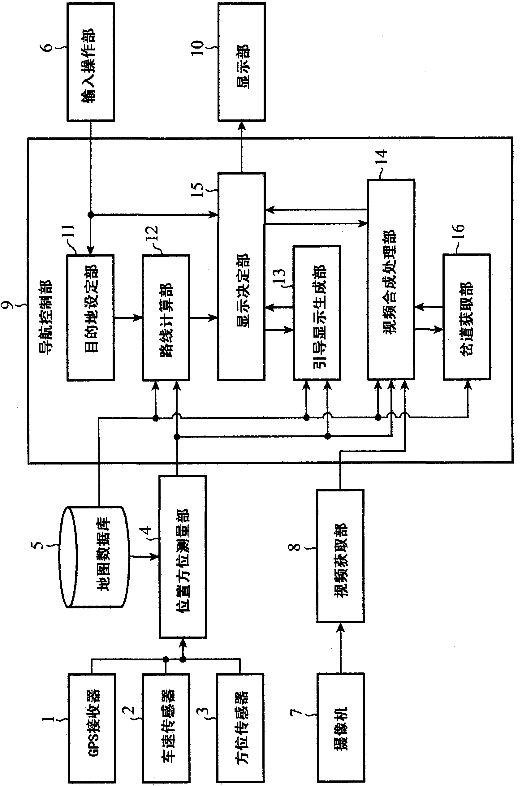
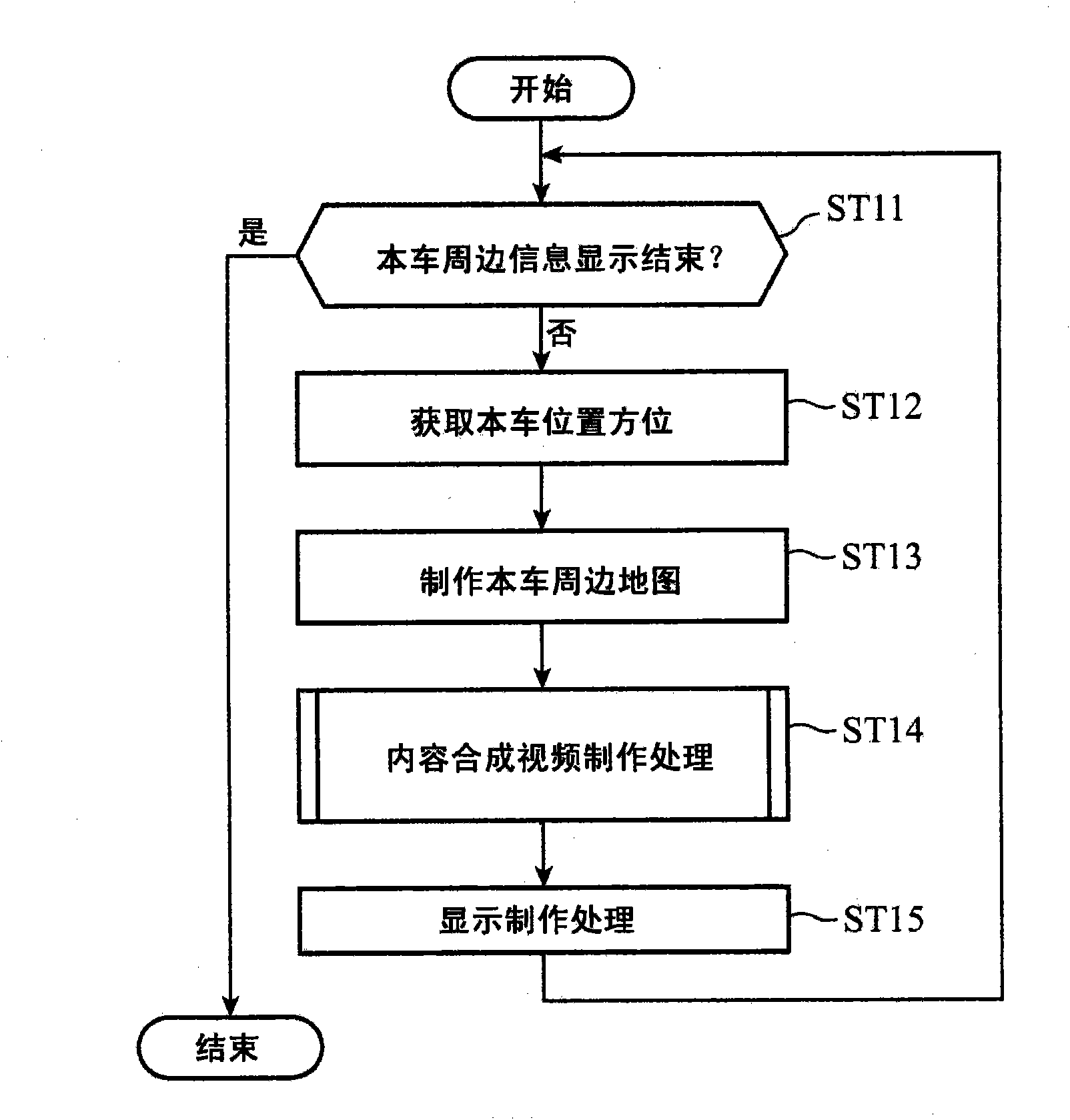
[0032] figure 1 It is a block diagram showing the configuration of a navigation device according to Embodiment 1 of the present invention, particularly a car navigation device applied to a vehicle. The car navigation device includes: a GPS (Global Positioning System: Global Positioning System) receiver 1, a vehicle speed sensor 2, an orientation sensor 3, a position and orientation measurement unit 4, a map database 5, an input operation unit 6, a camera 7, and a video acquisition unit 8 , a navigation control unit 9 , and a display unit 10 .
[0033] The GPS receiver 1 measures the vehicle's position by receiving radio waves from a plurality of satellites. The vehicle position measured by the GPS receiver 1 is sent to the position and direction measuring unit 4 as a vehicle position signal. The vehicle speed sensor 2 successively measures the speed of the own vehicle. The vehicle speed sensor 2 generally includes a sensor for measuring the rotational speed of tires. The s...
Embodiment approach 2
[0083] Figure 7 It is a block diagram showing the configuration of the car navigation device according to Embodiment 2 of the present invention. This car navigation device has a configuration in which the side road acquisition unit 16 is removed from the navigation control unit 9 of the car navigation device according to Embodiment 1, an intersection acquisition unit 17 is added, and the video synthesis processing unit 14 is changed to video synthesis. Processing section 14a.
[0084] The intersection acquisition unit 17 responds to an instruction from the video synthesis processing unit 14a, and acquires, from the map data read out from the map database 5, an intersection indicating an intersection existing in the guidance route from the vehicle position to the guidance target intersection. intersection data. The guidance route is obtained from the guidance route data acquired from the route calculation unit 12 by the video synthesis processing unit 14a. The intersection ...
Embodiment approach 3
[0094] The structure and Figure 7 The configuration of the car navigation device according to Embodiment 2 shown is the same.
[0095] Next, the operation of the car navigation device according to Embodiment 3 of the present invention will be described. The operation of the car navigation device according to the third embodiment is except for the content generation process of the road information (refer to Figure 5 ), the operation is the same as that of the car navigation device according to the second embodiment. Hereinafter, description will be made centering on parts that differ from the operations of the car navigation device according to Embodiment 2. FIG.
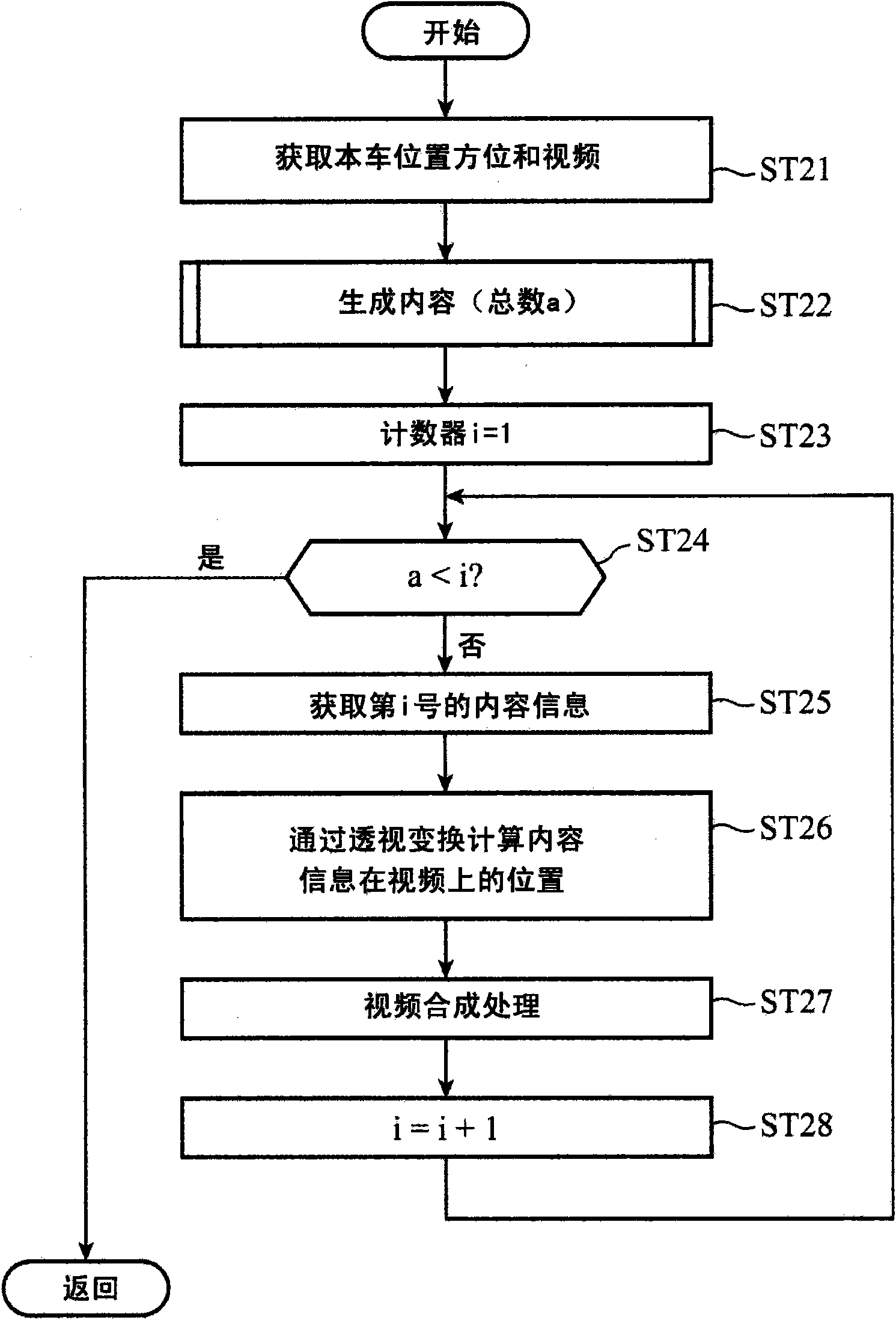
[0096] continue to use Figure 5 The flow chart shown for explaining the content creation process of road information in the car navigation device according to Embodiment 2 describes the content creation process of road information in the car navigation device according to Embodiment 3. In this road information...
PUM
 Abstract
Description
Claims
Application Information
 - R&D
- Intellectual Property
- Life Sciences
- Materials
- Tech Scout
- Unparalleled Data Quality
- Higher Quality Content
- 60% Fewer Hallucinations
Browse by: Latest US Patents, China's latest patents, Technical Efficacy Thesaurus, Application Domain, Technology Topic, Popular Technical Reports.
© 2025 PatSnap. All rights reserved.Legal|Privacy policy|Modern Slavery Act Transparency Statement|Sitemap|About US| Contact US: help@patsnap.com


