Rearview mirror device for vehicle

A technology for rear-view mirrors and vehicles, which is applied to vehicle components, optical observation devices, transportation and packaging, etc., can solve the problems such as the main body of the motor being unable to be fixed on the motor base, the tolerance becoming larger, and the loosening.

Active Publication Date: 2010-12-29
KK TOKAI RIKA DENKI SEISAKUSHO
View PDF4 Cites 3 Cited by
  • Summary
  • Abstract
  • Description
  • Claims
  • Application Information

AI Technical Summary

Problems solved by technology

[0008] However, in this rearview mirror device for a vehicle, if the tolerance caused by the size of the fitting cylinder of the motor base and the size of the motor main body becomes large, the main body of the motor may loosen with respect to the fitting cylinder of the motor base. Inability to properly secure the main body of the motor to the motor mount

Method used


Image

  • Rearview mirror device for vehicle
  • Rearview mirror device for vehicle
  • Rearview mirror device for vehicle

Examples


no. 1 approach

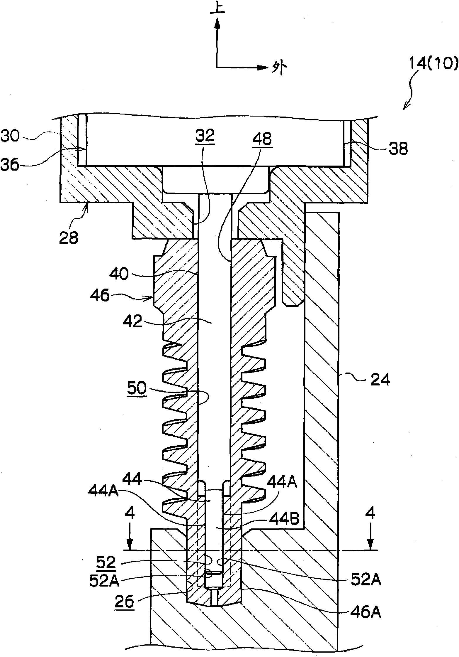
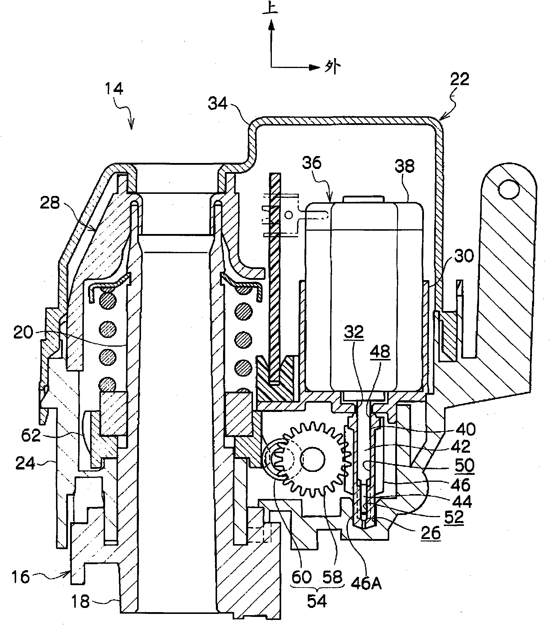
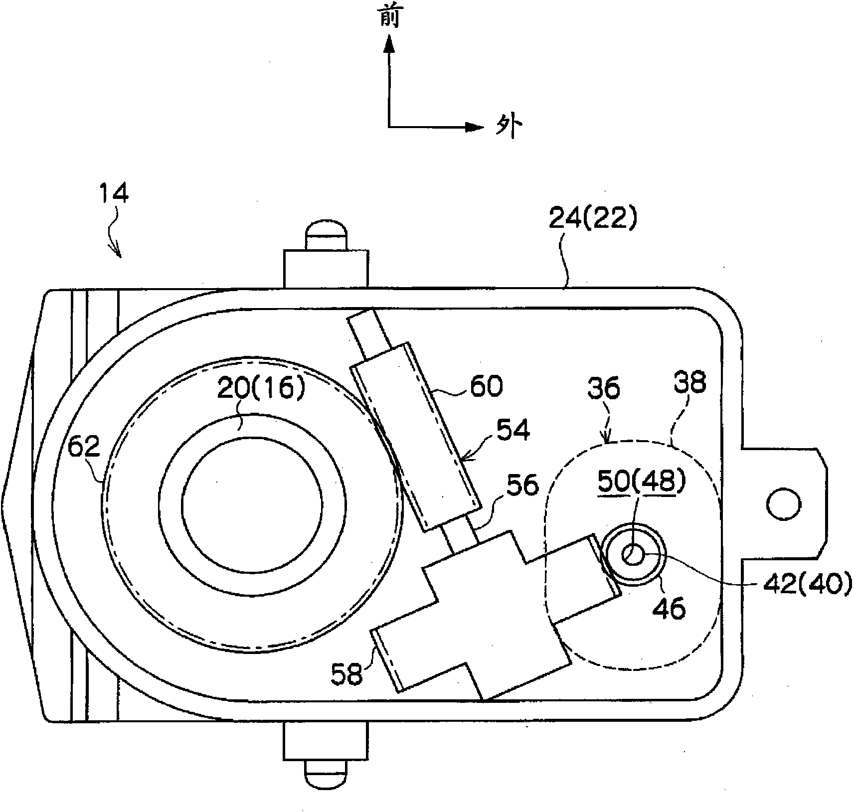
[0047] exist figure 2 1 is shown by a cross-sectional view of the main part of the door mirror device 10 (vehicle mirror device) according to the first embodiment of the present invention viewed from the rear of the vehicle. Figure 5 In FIG. 1 , it is represented by a front view of the door mirror device 10 viewed from the rear of the vehicle. In addition, in the drawings, the front of the vehicle is indicated by an arrow FR, the outward direction of the vehicle (both sides of the vehicle) is indicated by an arrow OUT, and the upward direction is indicated by an arrow UP.

[0048] The door mirror device 10 according to the embodiment of the present invention is provided at the vertical middle portion of a side door (particularly, a front door) serving as a door of a vehicle and at the vehicle front side end, and is arranged on the vehicle outer side.

[0049] Such as Figure 5 As shown, the door mirror device 10 includes a pillar 12 , and the inner end of the pillar 12 in ...


PUM


Abstract

The invention provides a rearview mirror device for a vehicle to make motion and sound stable. In a containing device (14) of a door rearview mirror device (10), a worm wheel (46) and an output shaft (40) are integrally rotated by driving a motor (36), so that a rearview mirror is rotated for containing or uprising. A main body (38) of the motor (36) is held in a holding cylinder (30) of a motor base (28). A shaft support part (46A) of the worm wheel (46) is in shaft support in a shaft support hole (26) of a shell (24) through a free rotation manner, and the output shaft and a clamping shaft (44) at the opposite side of the main body (38) are in shaft support in the shaft support hole (26) through the shaft support part (46A) in a free rotation manner. So that, no matter what load is input in the worm wheel (46) from a worm when the motor (36) is driven, the axle center of the worm wheel (46) is stable and the motion and the sound of the containing device (14) are stable.

Description

technical field [0001] The present invention relates to a vehicle rearview mirror device that accommodates or erects a vehicle rearview mirror. Background technique [0002] As a vehicle mirror device, there is a vehicle mirror device in which a housing member is rotated by a drive motor to house or erect a vehicle mirror (for example, refer to Patent Document 1). [0003] In this vehicle mirror device, the output shaft of the motor is inserted into the worm, and the helical gear meshes with the worm, and the output shaft of the motor and the worm are integrally rotated by driving the motor to rotate the helical gear. Furthermore, the lower end of the worm is rotatably pivoted on the housing part. [0004] However, in this vehicle mirror device, the output shaft of the motor is not inserted into the lower end of the worm, and the lower end (tip end) of the output shaft of the motor is not pivotally supported by the case member. Therefore, the axial center of the worm may b...

Claims


Application Information

Patent Timeline
Patent Type & Authority Applications(China)
IPC IPC(8): B60R1/072
Inventor 吉田茂树市川贵茂
Owner KK TOKAI RIKA DENKI SEISAKUSHO
Why Eureka
Try Eureka