
Free end revolving cup spinning machine

A rotor spinning machine, free-end technology, which is applied in the directions of free-end spinning machines, spinning machines, spinning machines with continuous winding, etc., can solve problems such as very difficult handling.

Active Publication Date: 2010-12-29
SAURER GERMANY GMBH & CO KG
View PDF19 Cites 13 Cited by
  • Summary
  • Abstract
  • Description
  • Claims
  • Application Information

AI Technical Summary

Problems solved by technology

Many parameters that can be adjusted in a defined way can only be dealt with with difficulty, especially for unskilled splice users, especially when they sometimes cancel each other out
Even for an experienced user, it can take a considerable amount of time to get a new splice to a satisfactorily fine tune

Method used


Image

  • Free end revolving cup spinning machine
  • Free end revolving cup spinning machine
  • Free end revolving cup spinning machine

Examples


Embodiment Construction

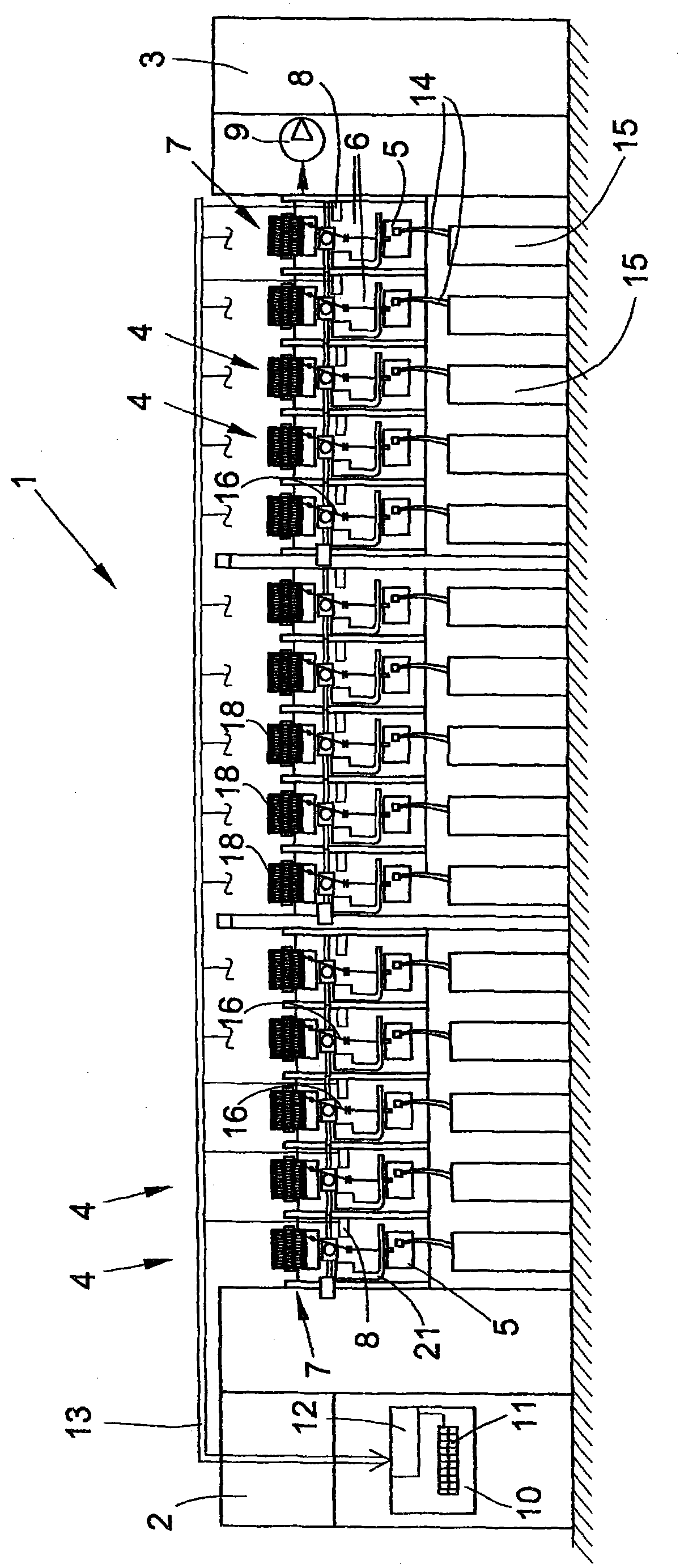
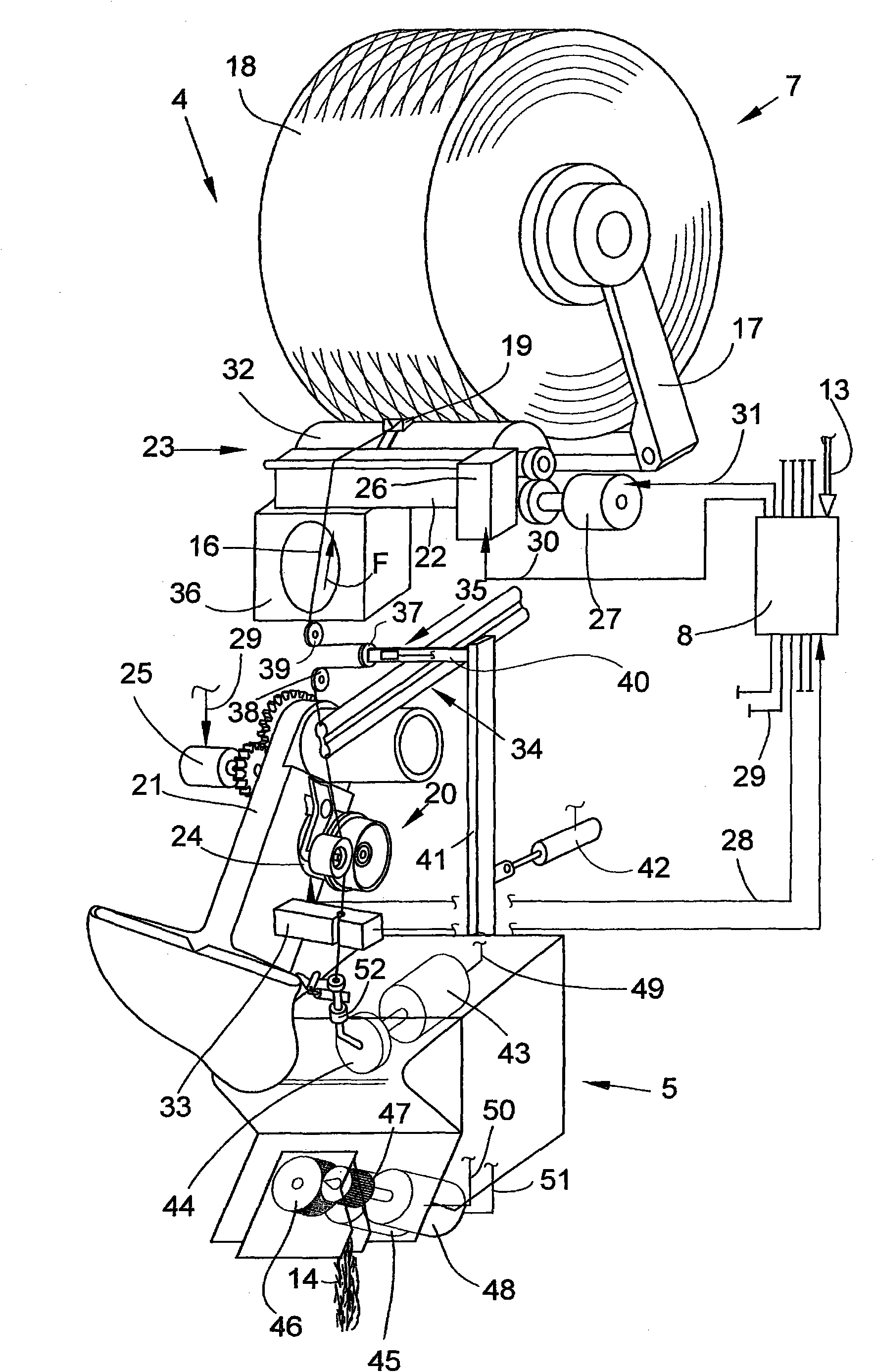
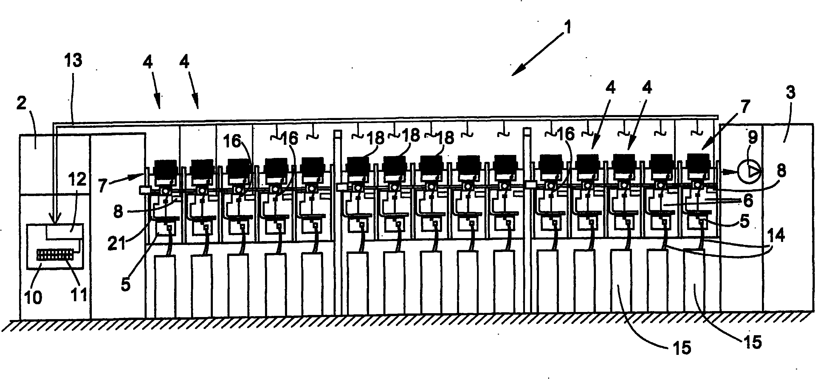
[0028] figure 1 Schematically shows a front view of an open-end rotor spinning machine 1 without splicing components, with a plurality of essentially self-contained workstations 4 arranged between two end frames 2 and 3 . The end frames 2, 3 of the open-end rotor spinning machine 1 (not shown in more detail as they are known) are connected by a continuous supply and treatment channel, for example for The vacuum channels of the spinning device 5 arranged in the area of ​​the workstation 4 , the electrical channels for the bus system 13 and the cable channels for supplying the electrical energy to the workstation 4 are supplied with negative spinning pressure. The yarn forming and winding mechanisms of the stations are secured by station housings 6 to these supply and processing channels, which are in essence the "backbone" of the textile machine 1 .

[0029] Station housings 6 are detachably arranged on the supply and processing channels, for example, each station housing has...


PUM


Abstract

The invention relates to a free end revolving cup spinning machine provided with a plurality of working positions, wherein each working position is provided with a control unit, is connected with a central control unit of the spinning machine, and has function elements, such as a free end spinning device and a yarn taking out unit. The function elements are structured and are actuated in the following manner: the function elements of the working station can automatically execute necessary splicing process after spinning is interrupted, or the function elements of the working station can automatically execute at least the operation procedures related to time during the splicing process. The central control unit in the free end revolving cup spinning machine is provided with a unit for inputting data and a computer unit. According to the invention, the computer unit (12) is arranged to use mathematical computing methods to compute the corresponding optimized basic regulation according to norms, which are related to splicing pieces and are easy to comprehend, and known spinning parameters, and conveys regulation to the work station (4) to complete the splicing process.

Description

technical field [0001] The invention relates to an open-end rotor spinning machine according to the preamble of claim 1 . Background technique [0002] Various types of open-end rotor spinning machines are used in the textile industry and are sometimes described in detail in numerous patent specifications. [0003] Open-end rotor spinning machines are known, for example, the stations of the open-end rotor spinning machine are configured such that they work essentially self-sufficiently during spinning. The stations of the open-end rotor spinning machine described, for example, in DE 10139075 A1 are each equipped with a large number of station-specific functional elements which can be actuated in a defined manner and which can be driven by individual drives. In a station configured in this way, after an interruption of spinning, the associated spinning device can automatically start spinning again via the functional element. In other words, the stations of this type of open...

Claims


Application Information

Patent Timeline
IPC IPC(8): D01H4/48
CPCD01H4/48D01H4/50
Inventor 古德龙·多
Owner SAURER GERMANY GMBH & CO KG
Learn More