Boiler powder generation system for burning lignite in power station gas duct and cooling tower machine

A technology of smoke towers and units, which is applied in the direction of combustion methods, combustion equipment, block/powder fuel preparation, etc., can solve problems such as potential safety hazards, and achieve the effects of increasing safety, increasing operational safety, and reliable system operation

Active Publication Date: 2011-01-05
HEILONGJIANG ELECTRIC POWER RES INST +1
View PDF6 Cites 0 Cited by
  • Summary
  • Abstract
  • Description
  • Claims
  • Application Information

AI Technical Summary

Problems solved by technology

[0003] The purpose of the present invention is to solve the problem that there is a great potential safety hazard in the burning of lignite by bituminous coal boilers in thermal power generation.

Method used


Image

  • Boiler powder generation system for burning lignite in power station gas duct and cooling tower machine
  • Boiler powder generation system for burning lignite in power station gas duct and cooling tower machine

Examples


specific Embodiment approach 1

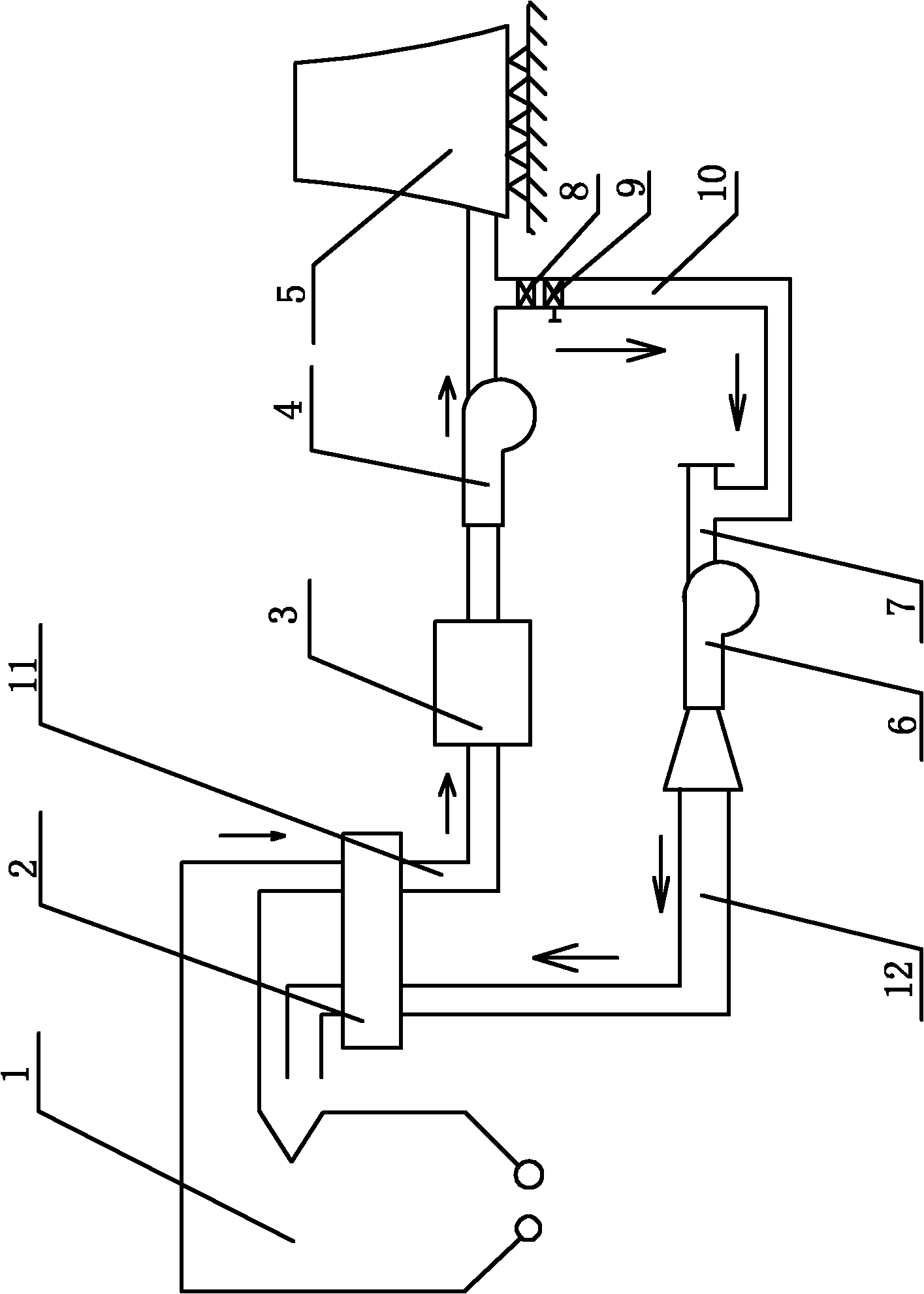
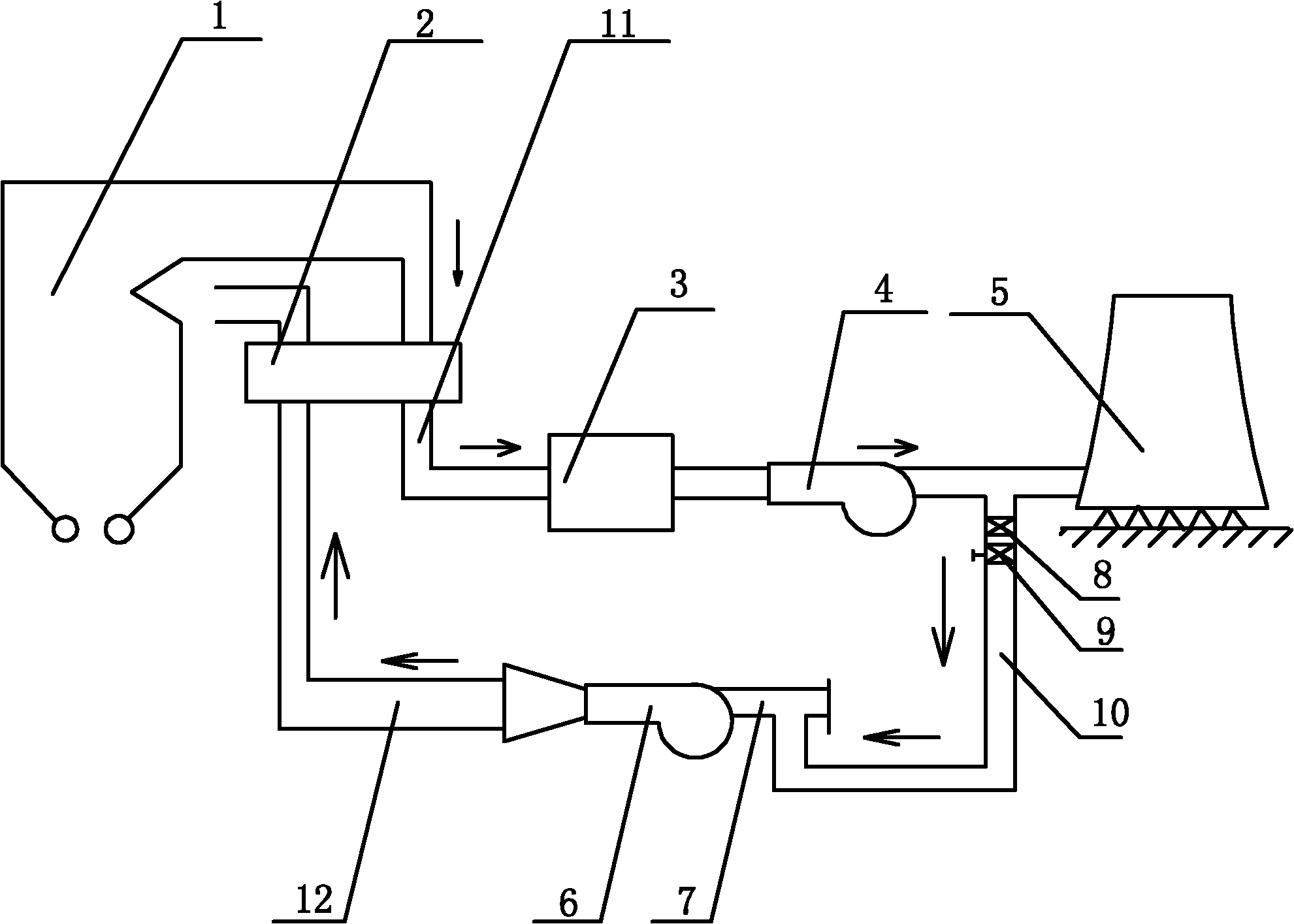
[0007] Specific implementation mode one: combine figure 1 Describe this embodiment. The system of this embodiment includes an air preheater 2, an electrical dust removal device 3, an induced draft fan 4, a smoke tower 5, a primary fan 6, a primary fan inlet duct 7, a first pipeline 11 and a second pipe Road 12, the outlet end of the cold furnace flue gas of the boiler 1 communicates with the inlet end of the first pipeline 11 through the hot end of the air preheater 2, and the outlet end of the first pipeline 11 is followed by the electrical dust removal device 3 and the induced draft fan 4 By communicating with the smoke tower 5, the system also includes a cold furnace smoke isolation baffle 8, a cold furnace smoke regulating baffle 9 and a cold furnace smoke pipeline 10, the inlet end of the cold furnace smoke pipeline 10 communicates with the first pipeline 11, The connection between the cold furnace smoke pipeline 10 and the first pipeline 11 is located between the induced...

specific Embodiment approach 2

[0009] Specific implementation mode two: combination figure 1 Describe this embodiment, the cold furnace smoke pipe 10 of this embodiment is a carbon steel pipe; Other components and connections are the same as those in the first embodiment.

[0010] Working principle: the cold furnace smoke gas discharged from the boiler 1 enters the first pipeline 11, and a part of the cold furnace smoke is sent into the cold furnace smoke pipe 10 by taking advantage of the high pressure head at the outlet of the induced draft fan 4, and the other part enters the smoke tower 5 Among them, the cold furnace flue gas entering the cold furnace flue pipe 10 is mixed with the cold air entering from the inlet duct 7 and then enters the primary fan 6, enters the second pipeline 12 from the outlet end of the primary fan 6, and passes through the air preheater 2 into the coal mill. The cold furnace smoke isolation baffle 8 and the cold furnace smoke adjustment baffle 9 are set in the cold furnace sm...


PUM


Abstract

The invention discloses a boiler powder generation system for burning lignite in a power station gas duct and cooling tower machine, which relates to a boiler powder generation system. The aim of the invention is to solve the problem that lignite in a bitumite-combusting boiler in the conventional thermal power generation causes a great safety hazards. An outlet end of a first pipe is communicated with a gas duct and cooling tower through a dust collector for electrical appliances and a draught fan in turn; the inlet end of a cold boiler gas duct is communicated with the first pipe; the communication part of the cold boiler gas duct and the first pipe is positioned between the draught fan and the gas duct and cooling tower; a cold boiler gas insulating baffle plate and a cold boiler gas regulating baffle plate are arranged from the inlet end of the cold boiler gas duct to the outlet of the cold boiler gas duct in turn; the outlet end of the cold boiler gas duct is communicated with an inlet air duct; the outlet end of the inlet air duct is communicated with the inlet end of a primary fan; the outlet end of the primary fan is communicated with the inlet end of a second pipe; and the outlet end of the second pipe is communicated with the cold end of an air preheater. The invention is used in technology for burning lignite in the power station gas duct and cooling tower machine.

Description

technical field [0001] The invention relates to a boiler pulverizing system. Background technique [0002] In recent years, with the changes in the coal market, more and more enterprises cannot get enough designed coal and must supplement a large amount of lignite. Because lignite has a high volatile content, is easy to catch fire, and has a low ignition point, especially when it enters the high-temperature inlet of the coal mill, it is more likely to catch fire and explode. Therefore, the current operation mode of coal-fired power plants mixed with lignite has great potential safety hazards. , based on this consideration, the necessary transformation must be carried out on the boiler pulverizing system to meet the long-term development of the enterprise. At the same time, some thermal power generation enterprises are located in alpine regions, and their winter operation is also responsible for supplying heat to the society. The safety of boiler operation in winter is direc...

Claims


Application Information

Patent Timeline
Patent Type & Authority Applications(China)
IPC IPC(8): F23K1/00
Inventor 孟繁兵束继伟闫承先李罡魏宝林黄朝阳金宏达金振山崔丽敏李景植张方时朱学成张欣刘延滨张永海徐雪峰牟郁慧刘伟王玉山王少青党文越
Owner HEILONGJIANG ELECTRIC POWER RES INST
Why Eureka
Try Eureka