Rack differential gear shaper transmission device
A kind of transmission device and differential technology, applied in the direction of gear tooth manufacturing device, gear cutting machine, gear teeth, etc., can solve the problems of easy wear of spiral guide rail, inability to adapt to processing helical gear, increase power consumption, etc., to overcome easy wear, Elimination of friction and good synchronization
- Summary
- Abstract
- Description
- Claims
- Application Information
AI Technical Summary
Problems solved by technology
Method used
Image
Examples
Embodiment 1
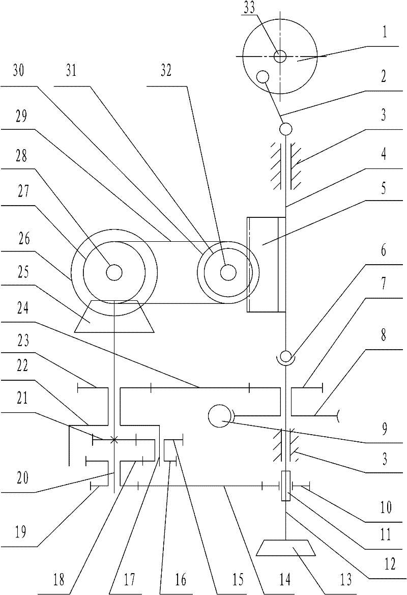
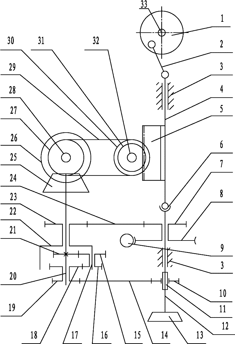
[0018] like figure 1 As shown, the rack and differential gear shaping machine transmission device includes a crank slider mechanism, a rack assembly 5, an intermediate transmission device, a differential transmission device, a worm and worm gear transmission mechanism, a cutter shaft, and a cutter shaft transmission mechanism;
[0019] The slider crank mechanism comprises a crank disc 1, a connecting rod 2, a slide block 4, and a crank shaft 33. The crank shaft 33 is supported by bearings on the gear shaping machine tool body 3 (the crank shaft 33 can rotate), and the crank disc 1 is fixed. Installed on the crank shaft 33, the crank disc 1 and the crank shaft 33 are perpendicular to each other, and one end of the crank shaft 33 is connected with the output shaft of the main motor of the gear shaping machine tool by a coupling or a transmission mechanism (the crank disc is controlled by the main motor of the gear shaping machine tool. Driven by a motor, the main motor of the ge...
Embodiment 2
[0030] It is basically the same as Embodiment 1, except that the cutter shaft transmission mechanism includes a sliding sleeve 11 and a cutter shaft driving wheel 10, the sliding sleeve 11 is fixedly installed on the cutter shaft 12, and the cutter shaft driving wheel 10 is sleeved on the sliding sleeve 11, Sliding sleeve 11 is provided with key or protruding slide block along the axial direction of cutter shaft 12, is provided with chute in the hole on the cutter shaft transmission wheel 10, and key or protruding slide block is positioned at chute (cutter shaft transmission Both the wheel 10 and the sliding sleeve 11 can slide linearly, and simultaneously the cutter shaft drive wheel 10 can drive the sliding sleeve 11 and the cutter shaft 12 to rotate together).
PUM
 Abstract
Description
Claims
Application Information
 - R&D
- Intellectual Property
- Life Sciences
- Materials
- Tech Scout
- Unparalleled Data Quality
- Higher Quality Content
- 60% Fewer Hallucinations
Browse by: Latest US Patents, China's latest patents, Technical Efficacy Thesaurus, Application Domain, Technology Topic, Popular Technical Reports.
© 2025 PatSnap. All rights reserved.Legal|Privacy policy|Modern Slavery Act Transparency Statement|Sitemap|About US| Contact US: help@patsnap.com


