Backlight device and display equipped with the device

A technology of backlight source and DC power supply, applied in the field of backlight source devices, can solve the problems of single operation confirmation and inspection of non-invertable circuits, complicated management of circuit substrates, and increased cost.

Inactive Publication Date: 2011-01-19
SHARP KK
View PDF6 Cites 3 Cited by
  • Summary
  • Abstract
  • Description
  • Claims
  • Application Information

AI Technical Summary

Problems solved by technology

Therefore, even if the specification of the inverter drive circuit 61 is the same, it is necessary to have a change based on the specification of the DC power supply circuit 53, which complicates the management of the circuit board as a component and leads to an increase in cost.
Furthermore, there arises a problem that operation confirmation and inspection cannot be performed as a single inverter circuit.

Method used


Image

  • Backlight device and display equipped with the device
  • Backlight device and display equipped with the device
  • Backlight device and display equipped with the device

Examples


Embodiment approach 1

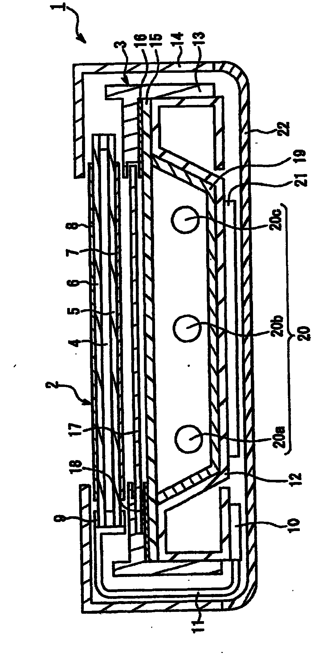
[0040] figure 1 It is a schematic cross-sectional view illustrating a backlight device according to an embodiment of the present invention and a liquid crystal display device including the backlight device. Such as figure 1 As shown, the liquid crystal display device 1 of this embodiment is provided with: figure 1 The upper side of the liquid crystal panel 2 (display unit) provided as the viewing side (display surface side); Backlight unit 3.

[0041] The liquid crystal panel 2 includes: a liquid crystal layer 4; a pair of transparent substrates 5, 6 sandwiching the liquid crystal layer 4; Also, a driver 9 for driving the liquid crystal panel 2 and a drive circuit 10 connected to the driver 9 via a flexible printed circuit board 11 are provided on the liquid crystal panel 2 .

[0042] The liquid crystal panel 2 is an active matrix liquid crystal panel, and the liquid crystal layer 4 can be driven on a pixel-by-pixel basis by supplying scanning signals and data signals t...

Embodiment approach 2

[0067] Next, as a second embodiment of the display device according to the present invention, an example in which the substrate structure of the lighting circuit for lighting the lamp is different will be described.

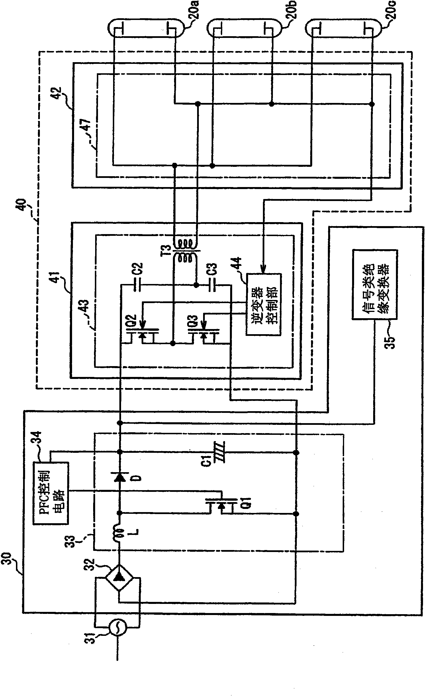
[0068] image 3 It is a block diagram showing a configuration of a lighting circuit of a backlight device used in a display device according to Embodiment 2 of the present invention. In addition, in the liquid crystal display device according to this embodiment, only the structure of the inverter unit of the lighting circuit is different, and the overall structure of the liquid crystal display device and the structure of the backlight device are the same as those of the first embodiment, so illustration and details are omitted. illustrate.

[0069] Such as image 3 As shown, a lighting circuit as a backlight device used in the liquid crystal display device described in Embodiment 2 is constituted by a power supply unit and an inverter unit 40 arranged on a powe...


PUM

PropertyMeasurementUnit
thicknessaaaaaaaaaa
thicknessaaaaaaaaaa
diameteraaaaaaaaaa

Abstract

Provided are a backlight device in which the design freedom concerning the disposal position of a circuit board on to which circuit components are mounted can be kept by simplifying the structure of a lamp as a lighting circuit and reducing the size of the circuit board, and a display equipped with the backlight device. The backlight device comprises a lamp (20), and a lighting circuit (21) generating a lighting drive voltage for driving lighting of the lamp (20). The lighting circuit (21) includes a DC power supply circuit (33) for generating a DC voltage from an input voltage, an inverter drive circuit (43) for converting a DC voltage outputted from the DC power supply circuit (33) into a high frequency voltage, and a boost section (T2) for boosting a high frequency voltage outputted from the inverter drive circuit (43) up to the lighting drive voltage of the lamp (20), and the DC power supply circuit (33) and the inverter drive circuit (43) are disposed on different circuit boards.

Description

technical field [0001] The present invention relates to a backlight device that obtains a lamp lighting driving voltage through an inverter circuit, and a display device using the backlight device. Background technique [0002] In recent years, liquid crystal display devices having advantages such as low power consumption, thin profile, and light weight have been widely used as display devices for televisions. A liquid crystal panel, which is a display element used in a display portion of a liquid crystal display device, is a so-called non-emissive display element that does not emit light by itself. Therefore, generally, a light source device called a backlight device is provided on the back of the liquid crystal panel, and the degree of transmission of light irradiated from the backlight device is controlled in the liquid crystal layer to display images. [0003] As a backlight device of a liquid crystal display device, it is required to irradiate the entire image display ...

Claims


Application Information

Patent Timeline
Patent Type & Authority Applications(China)
IPC IPC(8): H05B41/24G02F1/133G02F1/13357
CPCG02F1/133604G02F1/133615H05B41/2827
Inventor 张志芳
Owner SHARP KK
Why Eureka
Try Eureka