Vertical servo hydraulic tool rest

A hydraulic and vertical technology, applied in the field of mechanical processing, can solve the problems such as the inability to effectively guarantee the braking force, the gear teeth and the gear shaft are easily broken, and the transmission torque is small, so as to improve various performances, reduce the strength of the gears, and improve the transmission efficiency. Low torque effect

Active Publication Date: 2011-01-26
烟台环球机床装备股份有限公司
View PDF5 Cites 6 Cited by
  • Summary
  • Abstract
  • Description
  • Claims
  • Application Information

AI Technical Summary

Problems solved by technology

[0003] The existing technology does not use hydraulic pressure to tighten and loosen the brake, but connects the double toothed plate and the tool table through a key, and adds a rotating sleeve to the double toothed plate, and the rotating sleeve is connected to the vertical shaft through a nut rectangular thread transmission, so that the When the sprocket is engaged, the key restricts the rotation of the knife table and the rotating sleeve so that it can only move up and down. In this way, the brake is tightened and released, and the brake force cannot be effectively guaranteed, and the indexing is not reliable; at the same time, the step The motor drives the gear set to realize the rotation of the knife table. In order to achieve the required reduction ratio, the number of gear stages used is generally not less than 4, such as image 3 As shown, limited by the space, the gears are relatively small, and the gear shaft is also relatively thin, which leads to too many high-speed rotating bodies, large moment of inertia, low gear strength, and small transmission torque. Once the torque is slightly larger, the gear teeth and the gear shaft are very easy to break

Method used


Image

  • Vertical servo hydraulic tool rest
  • Vertical servo hydraulic tool rest
  • Vertical servo hydraulic tool rest

Examples


Embodiment Construction

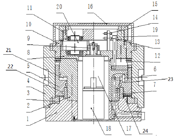
[0032] In the following, the present invention will be further described by using the following embodiments in conjunction with the accompanying drawings.

[0033] Depend on figure 1 As shown, the hydraulic support includes a base 1, a hollow vertical shaft 2, a transmission system, a bearing seat 8, an inner ring gear 10, a tool table 4, and a brake release assembly. The middle part of the base 1 is vertically fixed with a hollow vertical shaft 2, and the hollow vertical shaft The upper end of 2 is fixed with bearing seat 8, and transmission system wherein is fixed on the bearing seat 8. The transmission system mainly includes a servo motor 18, the output end of which is connected to a reducer 17. The reducer 17 is a high-precision planetary reducer. The reducer 17 and the servo motor 18 are fixed on the lower end surface of the bearing seat 8. Through the bearing seat 8, the driving gear 9 is fixed on it, and the transmission gear 20 which is externally meshed with the dri...


PUM


Abstract

The invention discloses a vertical servo hydraulic tool rest, which comprises a base, cylindrical vertical shafts, a drive system, inner gear rings, tool stages and a braking and loosening component, wherein the inner sides of the lower ends of the tool stages are fixedly with a movable fluted disc respectively, while upper ends are fixedly connected with the inner gear rings; fixed fluted discs are arranged on the upper end face of the base between the movable fluted discs and the vertical shafts; meshing teeth are arranged on the upper end faces of the movable fluted discs and the fixed fluted discs; the inner gear rings and the tool stages are driven by the drive system to rotate; the drive system comprises a speed reducer, a servo motor, a drive gear and a transmission gear; the speed reducer and the servo motor are connected with each other and are arranged below a bearing block; the drive gear is arranged above the bearing block, and is connected with an output shaft of the speed reducer; and the transmission gear is arranged on the bearing block, is externally meshed with the drive gear and is internally meshed with the inner gear rings. The vertical servo hydraulic tool rest has the characteristics of small moment of inertia, stable rotation, large output torque and relatively larger braking torque.

Description

technical field [0001] The invention relates to the field of mechanical processing, and more specifically relates to a vertical servo hydraulic tool holder with small moment of inertia, stable rotation, large output torque and relatively large braking torque. Background technique [0002] CNC tool post is an important functional part of CNC lathe, and its performance directly affects the overall performance of the machine tool. Now commonly used vertical tool holders, such as figure 2 As shown, the stepper motor is used to drive the gear set to rotate, the triple chainring is positioned, and the brake is tightened and released by the rectangular thread to drive the double chain to move up and down, which is realized by the interaction force between the triple chains. [0003] The existing technology does not use hydraulic pressure to tighten and loosen the brake, but connects the double toothed plate and the tool table through a key, and adds a rotating sleeve to the doubl...

Claims


Application Information

Patent Timeline
Patent Type & Authority Applications(China)
IPC IPC(8): B23B21/00
Inventor 徐国鹏王新基边辉曲志扬杨爱菊
Owner 烟台环球机床装备股份有限公司
Why Eureka
Try Eureka