A brake and accelerator pedal assembly

An accelerator pedal and pedal technology, which is applied in vehicle parts, transportation and packaging, foot start devices, etc., can solve the problems of drivers' mental and physical strain, fatigue, brake lag, and accidental stepping on the accelerator.

Active Publication Date: 2019-09-24
CHINA FIRST AUTOMOBILE
View PDF6 Cites 0 Cited by
  • Summary
  • Abstract
  • Description
  • Claims
  • Application Information

AI Technical Summary

Problems solved by technology

Therefore, every time switching between refueling and braking, the driver has to lift, move, and place the foot. If the number of times is too high, it will easily cause the driver's mental and physical tension and fatigue.
[0007] Further analysis shows that there are two obvious defects in the traditional scheme, which may lead to hidden dangers in driving safety
[0008] Defect 1: It may lead to the situation of "brake accidentally stepping on the accelerator"
[0013] Flaw 2: Brake lag

Method used


Image

  • A brake and accelerator pedal assembly
  • A brake and accelerator pedal assembly
  • A brake and accelerator pedal assembly

Examples


Embodiment Construction

[0039] The technical solutions of the present invention will be further explained and described below in the form of specific embodiments.

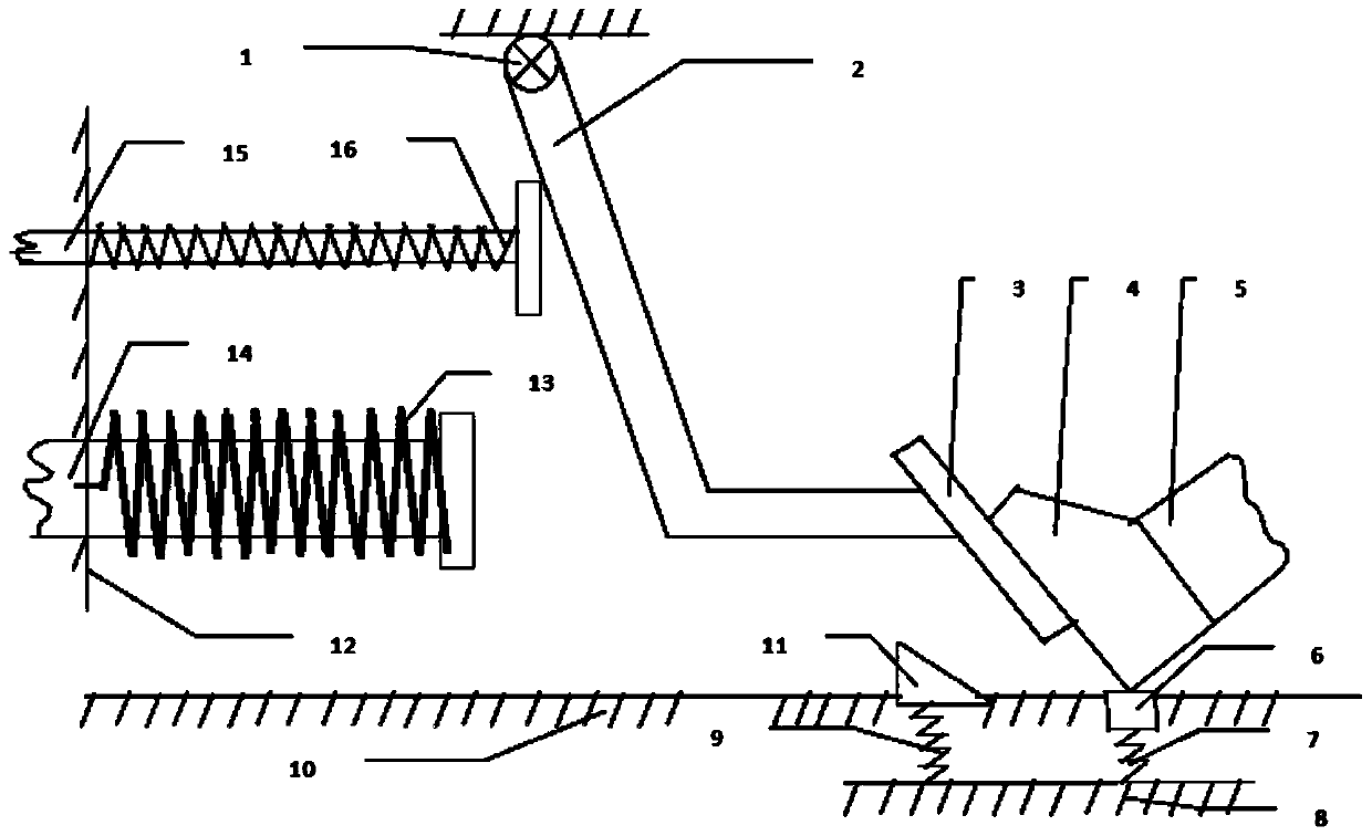
[0040] Such as figure 2 As shown, a brake and accelerator pedal assembly mainly includes: pedal 3, pedal connecting rod 2, pedal connecting rod fixing hinge 1, switch 6, switch return spring 7, accelerator limit block 11, accelerator limit block return Bit spring 9, brake push rod 14, brake push rod return spring 13, throttle push rod 15, throttle push rod return spring 16. The support base 8 for installing the return spring 7 of the switch and the return spring 9 of the throttle limit block.

[0041] The pedal 3 is fixed on the pedal link 2, and the pedal link 2 is connected with the cab front wall 12 through the pedal link fixing hinge 1 or is connected with a separate bracket.

[0042] Accelerator push rod 15 and brake push rod 14 are installed on the driver's cab cowl 12, and are positioned on the moving direction of pedal connecti...


PUM


Abstract

The invention discloses a brake and accelerator pedal assembly. The problem that an existing brake accelerator pedal adopts independent design, the fact that the pedaled pedal is an accelerator or a brake needs to be judged during braking, and the situation that the accelerator is pedaled mistakenly occurs often in the emergency situation is solved. The assembly has only one set of pedal mechanism, the pedal mechanism is hung on the front of a cab or an independent bracket through a hinge and is composed of a pedal connecting rod, a pedal, a switch, an accelerator limiting block, a brake limiting block, a corresponding electronic accelerator sensor circuit, a accelerator limiting block control circuit, an accelerator ejector rod return spring and a brake ejector rod return spring. The accelerator limiting block is higher than a cab floor when the accelerator limiting block control circuit is switched on, an accelerator limiting action is achieved, the accelerator limiting block is lower than the cab floor when the accelerator limiting block control circuit is broken, and the limiting action is not achieved. After a heel lands to the ground and pedals on the switch, the pedal is the accelerator pedal, and after the heel is off the ground and the switch is bounced, the pedal is the brake pedal.

Description

technical field [0001] The invention belongs to the field of automobile design and manufacture, and in particular relates to a brake and accelerator pedal assembly. Background technique [0002] At present, the gas pedal and the brake pedal of the automobile (hereinafter referred to as its scheme is the traditional scheme), its operating action specification is: [0003] 1) [Come on] When the heel touches the ground, the ankle joint exerts force, and the sole of the foot gently presses down on the accelerator pedal. At this time, the bottom of the sole of the foot slides backward relative to the surface of the pedal. This action is called "click" below. [0004] 2) [Only oil collection without braking] When the heel touches the ground, the ankle joint exerts force to lift the sole of the foot from the accelerator pedal. At this time, the bottom of the sole of the sole slides forward relative to the surface of the pedal. [0005] 3) [Switch from refueling to braking] such as...

Claims


Application Information

Patent Timeline
Patent Type & Authority Patents(China)
IPC IPC(8): B60K26/02B60T7/06
Inventor 王文阁
Owner CHINA FIRST AUTOMOBILE
Why Eureka
Try Eureka