Concentric winding type automatic conversion device for winding mold

A technology of automatic conversion and winding mode, which is applied in coil manufacturing, electrical components, inductor/transformer/magnet manufacturing, etc. line etc.

Pending Publication Date: 2018-11-13
SHANDONG ZHONGJIE INTELLIGENT EQUIP CO LTD
View PDF0 Cites 0 Cited by
  • Summary
  • Abstract
  • Description
  • Claims
  • Application Information

AI Technical Summary

Problems solved by technology

[0002] In the process of winding winding, two winding molds are fixed at an angle on the winding disk of the existing non-cross winding machine, and the whole winding mold deviates from the center of rotation. When winding, the winding mold rotates eccentrically, which c

Method used


Image

  • Concentric winding type automatic conversion device for winding mold
  • Concentric winding type automatic conversion device for winding mold
  • Concentric winding type automatic conversion device for winding mold

Examples


specific Embodiment approach

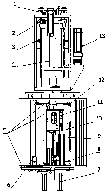
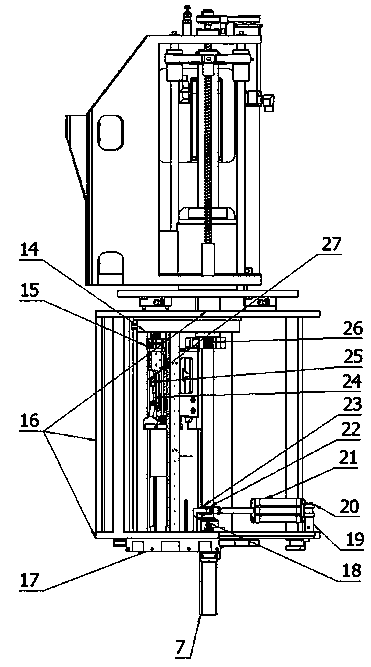
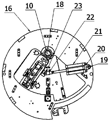
[0012] Specific implementation method: reference figure 1 , Figure 5 . The mold sinking motor 1 drives the screw 3 to rotate so that the sinking mold slider 2 fixedly connected with the screw nut drives the sinking mold shaft 4 to move up and down, and the lower end of the sinking mold shaft 4 is equipped with a latch lock block 26; the right winding mold 7 is fixedly connected At the lower end of the transposition support 5, the left winding die 9 distributed at an angle with the right winding die 7 is fixedly connected below the lifting support 11; the two sides of the lifting support 11 are equipped with guide rail sliders 24 and guide rail clamps 25, and the guide rail The slide block 24 and the guide rail clamp 25 cooperate with the guide rail 27 mounted on the transposition bracket 5, and the switch of the guide rail clamp 25 can produce two states of fixing and sliding with the guide rail 27; , when the left winding die 9 is located at the center of the winding brack...


PUM


Abstract

The invention belongs to the technical field of electric machinery and particularly relates to a concentric winding type automatic conversion device for a winding mold for non-cross winding machine. The concentric winding type automatic conversion device is characterized in that a transposition rotating shaft is mounted on a transposition bracket, and two ends of the transposition rotating shaft are respectively hinged with an upper rotating shaft block and a lower rotating shaft block which are mounted on the winding bracket; and the rear end of an transposition air cylinder is hinged with anair cylinder rotating shaft fixedly connected to the winding bracket, and a piston rod of the transposition air cylinder is hinged with a pin shaft block fixedly connected to the transposition bracket. A left winding mold and a right winding mold which are mounted on the transposition bracket and are distributed in an included angle manner can be driven by the transposition air cylinder to move back and forth along the horizontal direction by taking the transposition rotating shaft as a center. When the piston rod of the transposition air cylinder stretches out, the center of a right windingmold is coincided with the center of the winding bracket, and when the piston of the transposition air cylinder shrinks back, the center of the right winding mold is coincided with the center of the winding bracket, so that the effects of high-speed winding and precise winding displacement can be achieved.

Description

technical field [0001] The invention belongs to the technical field of electrical machinery, and in particular relates to an automatic conversion device for concentric winding of winding dies on a non-cross winding machine. Background technique [0002] In the process of winding winding, two winding molds are fixed at an angle on the winding disk of the existing non-cross winding machine, and the whole winding mold deviates from the center of rotation. When winding, the winding mold rotates eccentrically, which cannot be realized. High-speed winding, and when the winding die rotates eccentrically, the amount of wire used is uneven, resulting in large changes in the elasticity of the enameled wire, which cannot meet the requirements of high-speed winding and precision wiring. Contents of the invention [0003] The object of the present invention is to provide a concentric winding automatic conversion device for winding molds capable of realizing high-speed winding and preci...

Claims


Application Information

Patent Timeline
IPC IPC(8): H01F41/09H01F41/098
CPCH01F41/09H01F41/098
Inventor 王晓东林俊岐王东明成学虎李君王雷吕佐东牟文超徐海洁李光新
Owner SHANDONG ZHONGJIE INTELLIGENT EQUIP CO LTD
Why Eureka
Try Eureka