Unwinding machine, insulated wire production device and unwinding method

A pay-off machine and wire technology, applied in the direction of transportation and packaging, delivery of filamentous materials, thin material processing, etc., can solve the problems affecting the production efficiency of insulated wires, wire accumulation and winding, and inconvenient production recovery, etc.

Pending Publication Date: 2020-05-19
苏州宇盛电子有限公司
View PDF0 Cites 0 Cited by
  • Summary
  • Abstract
  • Description
  • Claims
  • Application Information

AI Technical Summary

Problems solved by technology

If the wire breaks during the production process, and the winding hub continues to pay off, the wires will be piled up and entangled, making it difficult to resume production and affecting the production efficiency of insulated wires

Method used


Image

  • Unwinding machine, insulated wire production device and unwinding method
  • Unwinding machine, insulated wire production device and unwinding method
  • Unwinding machine, insulated wire production device and unwinding method

Examples


Embodiment 1

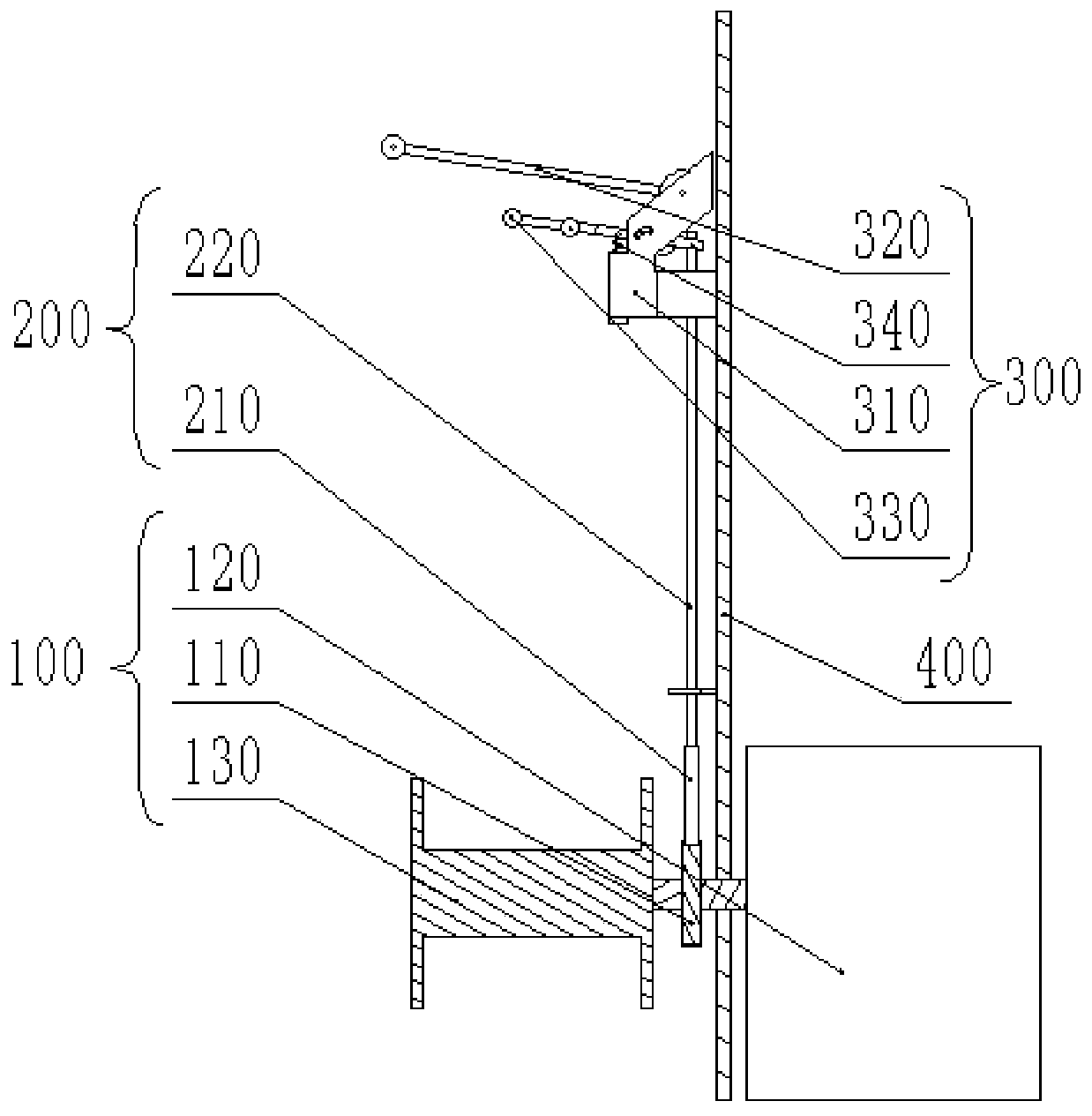
[0042] Such as figure 1 As shown, the pay-off machine provided by the embodiment of the present invention includes: a pay-off mechanism 100, a brake mechanism 200, and a transmission mechanism 300; the transmission mechanism 300 is connected to the brake mechanism 200; to the transmission mechanism 300 and output through the transmission mechanism 300; the transmission mechanism 300 is configured to drive the braking mechanism 200 in an off-line state to brake the wire-releasing mechanism 100.

[0043] Specifically, the wire output by the pay-off mechanism 100 is wound around the transmission mechanism 300. When the wire falls off on the transmission mechanism 300, or when the wire breaks, the transmission mechanism 300 drives the braking mechanism 200, thereby passing through the braking mechanism 200. Brake the pay-off mechanism 100 to stop the pay-off mechanism 100 from paying out.

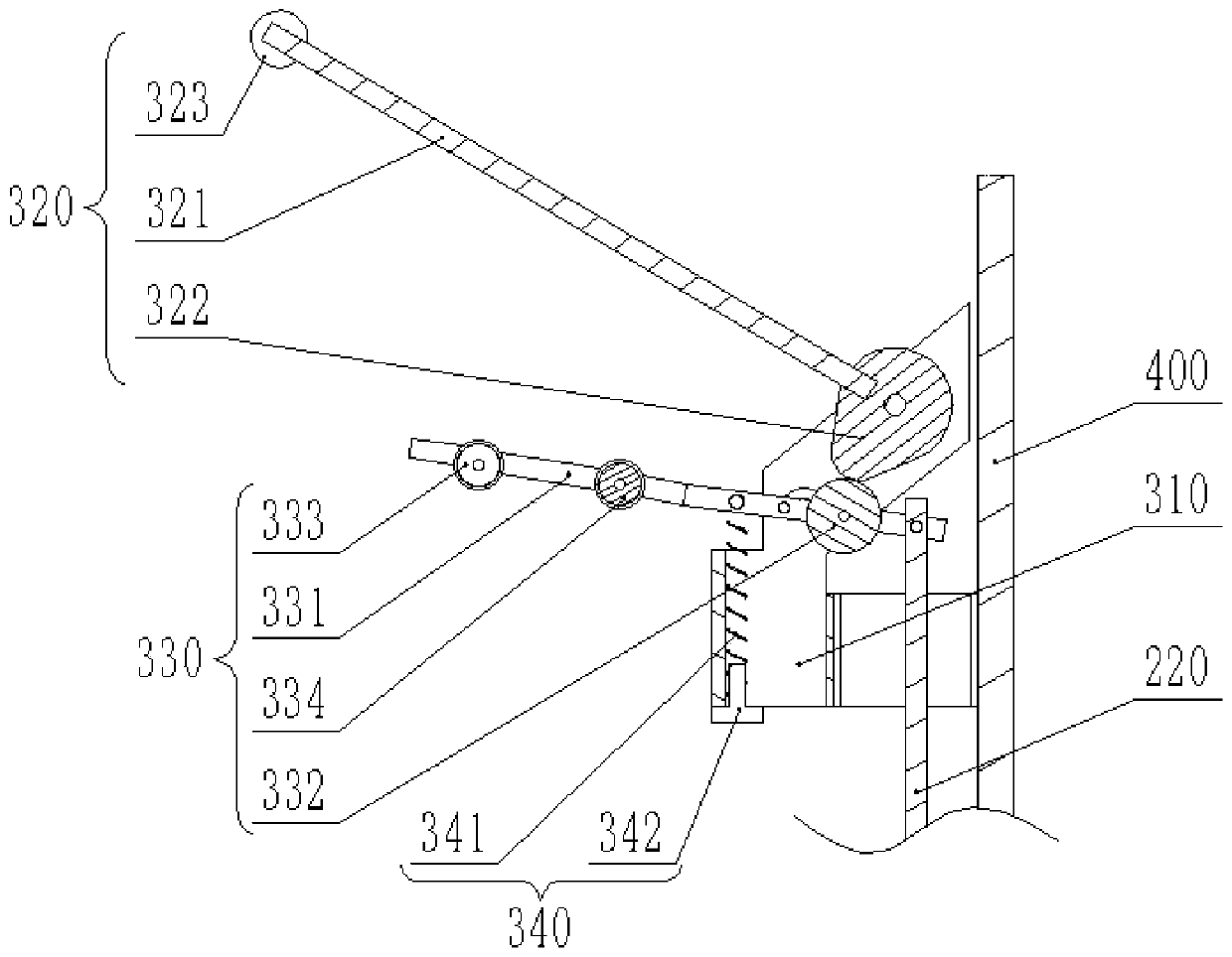
[0044] Such as figure 1 with figure 2 As shown, in the embodiment of the present invent...

Embodiment 2

[0059] The insulated wire production device provided in the embodiment of the present invention is equipped with the wire pay-off machine provided in the second embodiment. Among them, the insulated wire production device has the same technical effect as the pay-off machine, so it will not be repeated here.

Embodiment 3

[0061] Such as figure 1 with figure 2 As shown, the wire releasing method provided by the embodiment of the present invention includes the following steps: the wire is output from the wire feeding mechanism 100 through the conveying mechanism 300; when the wire is wound around the conveying mechanism 300, the conveying mechanism 300 drives the braking mechanism 200 releases the brake on the pay-off mechanism 100; when the wire is disengaged from the guide mechanism 300, the guide mechanism 300 drives the brake mechanism 200 to brake the pay-off mechanism 100. Using the pay-off machine provided in Embodiment 1, when the wire breaks or breaks away from the guide mechanism 300, the brake mechanism 200 is driven by the guide mechanism 300 to brake the pay-off mechanism 100, thereby avoiding the accumulation and entanglement of the wire. It is convenient for maintenance and quick recovery of production, which can shorten the troubleshooting time of the pay-off machine and improve...


PUM


Abstract

The invention provides an unwinding machine, an insulated wire production device and an unwinding method, and relates to the technical field of insulated wire production. The unwinding machine comprises an unwinding mechanism, a braking mechanism and a conveying and guiding mechanism; the conveying and guiding mechanism is in transmission connection with the braking mechanism; wires on the unwinding mechanism is conveyed to the conveying and guiding mechanism and is conveyed out through the conveying and guiding mechanism; and the conveying and guiding mechanism is configured to drive the braking mechanism in a wire-off state so as to brake the unwinding mechanism. According to the unwinding machine, the unwinding mechanism can be automatically braked in the wire-off state, and wire accumulating and winding caused by continuous unwinding of the unwinding machine in the abnormal state are avoided.

Description

technical field [0001] The invention relates to the technical field of insulated wire production, in particular to a wire pay-off machine, an insulated wire production device and a wire pay-off method. Background technique [0002] When the pay-off machine is paying off, if there is a disconnection problem, the pay-off machine cannot brake in time, which will lead to continuous pay-off, which will cause insufficient tension of the wire and affect the normal operation of production. In the prior art, in order to avoid wire breakage when pulling and unwinding, a motor is used to drive the pay-off hub to rotate, thereby releasing the wire from the pay-off hub. If the wire breaks during the production process, and the winding hub continues to pay off, the wire will be piled up and entangled, making it difficult to resume production and affecting the production efficiency of the insulated wire. Contents of the invention [0003] The purpose of the present invention is to provi...

Claims


Application Information

Patent Timeline
Patent Type & Authority Applications(China)
IPC IPC(8): B65H59/04
CPCB65H59/04B65H2701/341
Inventor 周朝洪
Owner 苏州宇盛电子有限公司
Why Eureka
Try Eureka