
Block removing device and method

A technology of deblocking and blocking, applied in the field of deblocking devices, which can solve the problems of blurred and lost pictures, etc.

Inactive Publication Date: 2011-02-02
MSTAR SOFTWARE R&D (SHENZHEN) LTD +1
View PDF0 Cites 5 Cited by
  • Summary
  • Abstract
  • Description
  • Claims
  • Application Information

AI Technical Summary

Problems solved by technology

In the existing display device, the input video signal received by the display device is usually processed by a low-pass filter 11 to output the video signal output after filtering, but wrong processing will cause the entire picture to blur and lose many details of the picture
In addition, the existing technology must know the block boundary position in advance in order to correctly deblock, but this is difficult to do in some cases at the receiving end, such as: analog television (ATV for short)

Method used


Image

  • Block removing device and method
  • Block removing device and method
  • Block removing device and method

Examples


Embodiment Construction

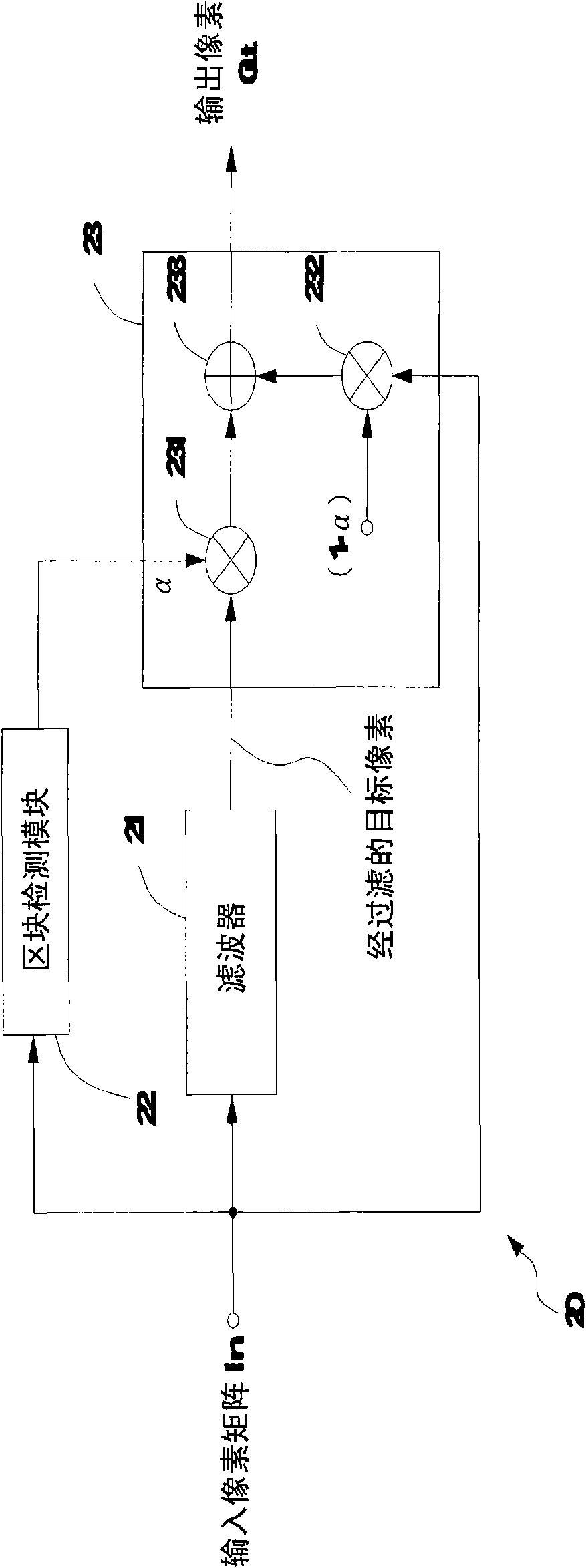
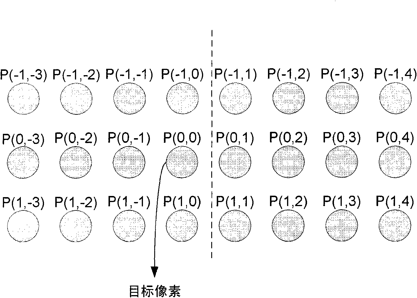
[0027] figure 2 A circuit block diagram of a deblocking device 20 according to an embodiment of the present invention is shown, including a filter 21 , a block detection module 22 and a mixing unit 23 . The deblocking device 20 receives the MxN pixel matrix In, and outputs a deblocked pixel Out after performing deblocking processing on a target pixel in the pixel matrix In. Each pixel has a pixel value P(i, j), wherein i=1 to M, j=1 to N, and each pixel value includes the R value, G value or B value of the pixel in the R-G-B color gamut, such as R value, The G value or the B value are integers ranging from 0 to 255, respectively. In another embodiment, the pixel value P(i, j) represents the Y value of a pixel in the Y-U-V color gamut; or, the pixel value P(i, j) represents the Y value of a pixel in the Y-Cb-Cr color gamut Y value. Those skilled in the art can understand the conversion between the pixel value in the R-G-B color gamut and the Y-U-V color gamut or the Y-Cb-Cr...


PUM


Abstract

The invention relates to a block removing device and a method. The block removing device comprises a filter, a block detecting module and a mixing unit, wherein the filter is used for receiving a target pixel in a pixel matrix to generate a filtered target pixel; the block detecting module is used for generating a block removing strength factor according to the pixel matrix; and the mixing unit is used for receiving the target pixels and the filtered target pixel and mixing the target pixels and the filtered target pixel to generate an output pixel according to the block removing strength factor.

Description

【Technical field】 [0001] The present invention relates to image processing, in particular to a deblocking device and method. 【Background technique】 [0002] When processing digital video image signals, the digital video image signals are generally encoded and compressed for high-speed transmission in channels with limited bandwidth. For example, the Moving Picture Experts Group (MPEG) is a block-based video compression format. [0003] After the video image signal is encoded and compressed, it is sent to the signal decoder through the transmission channel, and the signal decoder decodes and decompresses the video image signal. However, after the video image signal is reconstructed by the signal decoder, annoying blocking artifacts often occur, making the user aware of an obvious blocking boundary. This is mainly because the image display signal is based on Blocks are encoded in units. [0004] figure 1 Shown as a block diagram of an existing deblocking device. In the ex...

Claims


Application Information

Patent Timeline
IPC IPC(8): H04N7/26H04N19/117H04N19/176H04N19/182
Inventor 许瀚仁李维国
Owner MSTAR SOFTWARE R&D (SHENZHEN) LTD
Learn More