Vertical vacuum water quenching furnace

A technology of water quenching furnace and vacuum, which is applied in the field of vertical vacuum water quenching furnace, which can solve the problems of low productivity, high heating temperature, large direct heat dissipation of furnace tank, etc., and achieve the effect of large heating zone size and high heating temperature

Inactive Publication Date: 2011-02-09
BEIJING EXEMOO INDAL FURNACE MFG
View PDF10 Cites 24 Cited by
  • Summary
  • Abstract
  • Description
  • Claims
  • Application Information

AI Technical Summary

Problems solved by technology

But its limitations are: (1) The heating temperature cannot be higher than 1100°C; (2) The size of the effective heating zone is limited (diameter 160mm, length 300mm), so the furnace capacity is limited; (3) High temperature higher than 900°C during quenching The retort is completely exposed, causing large heat dissipation to the working environment and high energy consumption; (4) After quenching, it is necessary to wait for the retort to cool for 1 to 2 hours before continuing to install the furnace, and the productivity is low
[0005] In a word, in the above two existing technologies, the former has high heating temperature, large furnace loading capacity, direct heat dissipation without furnace tank, but the workpiece transfer time is long; the latter workpiece transfer time is short, but the heating temperature and furnace loading capacity are limited, The furnace can directly dissipate heat

Method used


Image

  • Vertical vacuum water quenching furnace
  • Vertical vacuum water quenching furnace
  • Vertical vacuum water quenching furnace

Examples


Embodiment approach

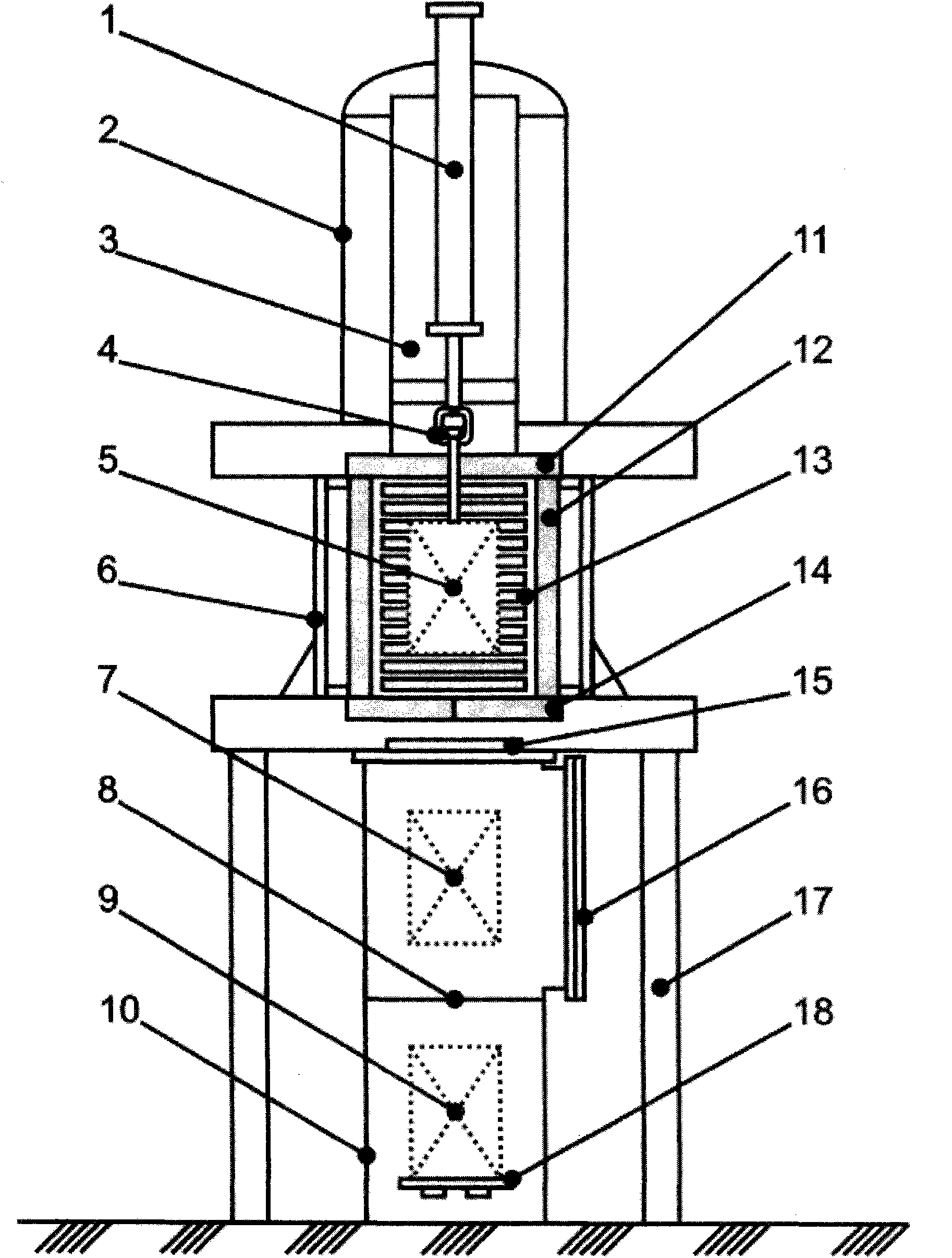
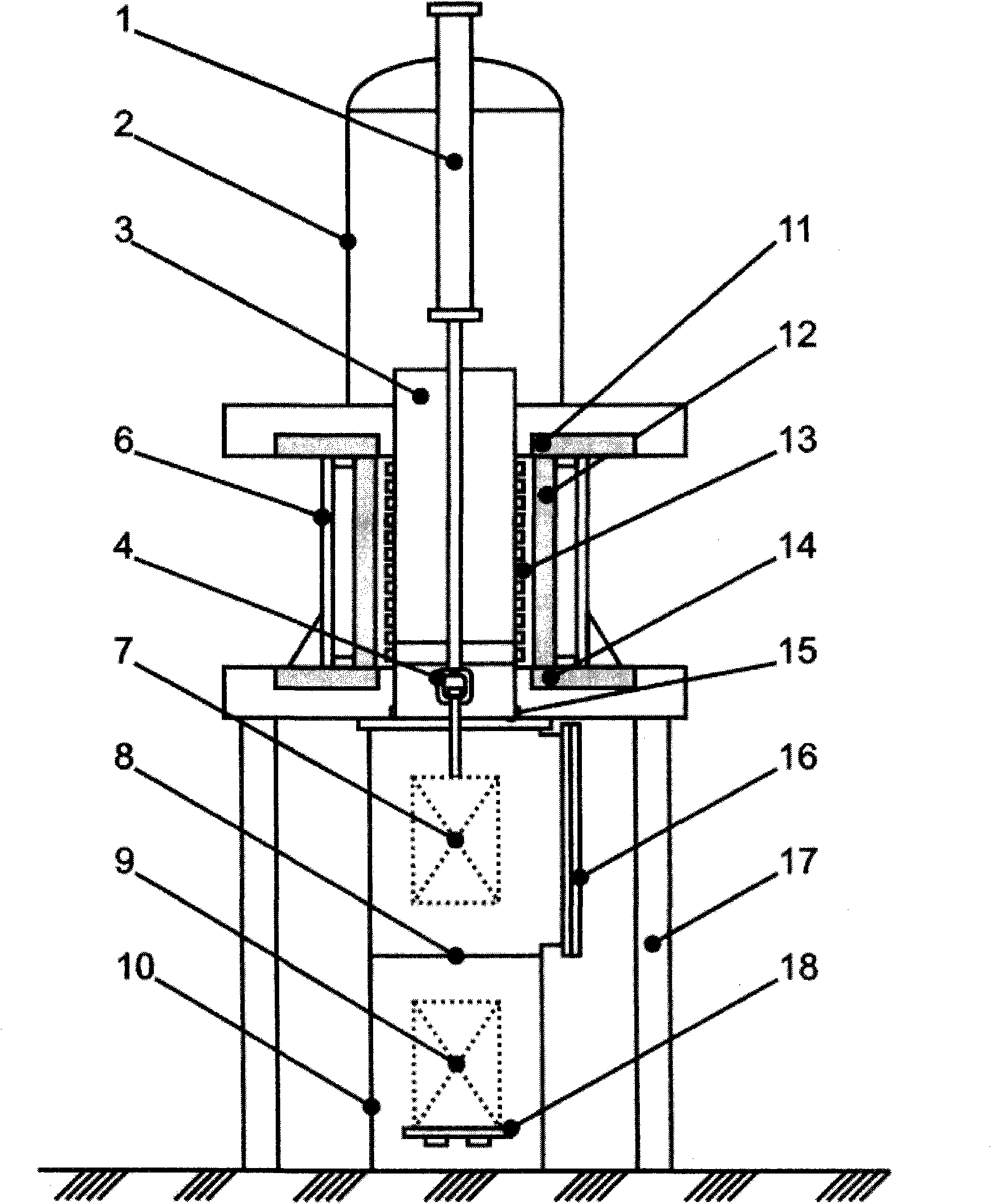
[0047] As another implementation method of the present invention, the lower heat-insulation door and the lower airtight door can be combined into one body, and a lower heat-insulation airtight door can realize heat insulation and sealing at the same time.

[0048] The third implementation method

[0049] In the present invention, the quenching mechanism located above the furnace body is equipped with the charge and the isolated air pump at the same time. As the third implementation method of the present invention, these two mechanical actions can be separated, and the mechanism located above the furnace body is only mounted with the isolated air pump. The lifting mechanism located in the quenching water tank completes the mechanical action of lifting the charge into and out of the heating chamber and the quenching water tank. In this case, the lower insulation door and the lower airtight door cannot be combined into one body. The lower insulation door must adopt a double-open ...


PUM


Abstract

The invention belongs to the technical field of vacuum thermal treatment equipment and discloses a vertical vacuum water quenching furnace. A heating chamber is of an internal thermal structure and is provided with an upper thermal insulation door, a lower thermal insulation door and a lower sealing door; after lifting furnace charge is heated, a quenching mechanism arranged at the top of the furnace quenches the furnace charge into a quenching trough arranged at the bottom of the furnace directly and vertically under the condition that all doors are not closed; the quenching mechanism is provided with a follow-up insulation air pumping cylinder, located above the upper thermal insulation door during heating, and falling on the doorway of the lower thermal insulation door during quenching in order to prevent water vapor generated by quenching from polluting the heating chamber; and the quenching trough arranged below the heating chamber is provided with a hoisting mechanism for transporting the furnace charges vertically. The invention solves the technical problems of long work transfer time of a horizontal vacuum water quenching furnace, limits of heating temperature and an effective heating zone size of an external thermal vacuum water quenching furnace, and the like.

Description

technical field [0001] The invention relates to the field of vacuum heat treatment equipment, in particular to a vertical vacuum water quenching furnace. Background technique [0002] At present, the vacuum quenching furnaces with mature technology and widely used are mainly vacuum oil quenching furnaces and vacuum high pressure gas quenching furnaces, which cannot meet the technical requirements of water quenching for some materials (such as titanium alloys, beryllium bronze, elastic alloys, stainless steel, etc.). There are still few application examples of vacuum water quenching furnace. The basic technical requirements of the vacuum water quenching furnace: (1) When heating, the heating chamber and the quenching water tank should be completely isolated from the aspects of heat transfer and airtightness. Because the working temperature of the heating chamber is much higher than the boiling point of water, the pressure of the heating chamber is much lower than (2) When qu...

Claims


Application Information

Patent Timeline
Patent Type & Authority Applications(China)
IPC IPC(8): C21D1/62C21D1/63
Inventor 卢国旺高宁高文栋
Owner BEIJING EXEMOO INDAL FURNACE MFG
Why Eureka
Try Eureka