Equipment for migratory fish breeding

A breeding, circular technology, applied in fish farming, mobile filter element filters, animal husbandry, etc., can solve problems that do not involve the composition of channels and circulating flow in the tank

Inactive Publication Date: 2011-02-09
鹫山 一郎
View PDF4 Cites 10 Cited by
  • Summary
  • Abstract
  • Description
  • Claims
  • Application Information

AI Technical Summary

Problems solved by technology

However, the purpose of the invention in this document is to raise non-migratory fish such as flounder, tiger fish, and tiger porpoise in still water, and it does not involve the channel configuration and circulation flow in the tank that are useful for breeding migratory fish, and the basic configuration is different from the present invention.

Method used


Image

  • Equipment for migratory fish breeding
  • Equipment for migratory fish breeding
  • Equipment for migratory fish breeding

Examples


Embodiment approach 1

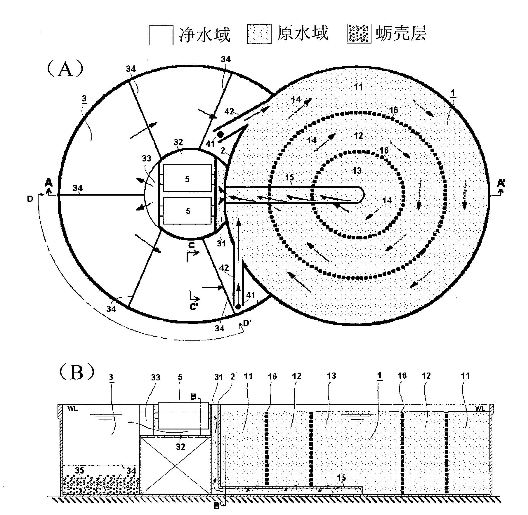
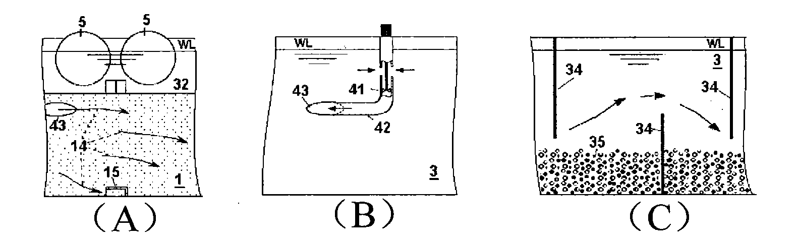
[0039] The water passage is provided at the bottom of the breeding tank, has an opening on the side where the circulating flow hits, and a part of the circulating flow flows in through the opening. This embodiment corresponds to the second aspect of the invention.

[0040] Since the water passage is installed across the circulation flow near the bottom of the breeding tank, the circulation flow collides with the side surfaces of the rectangular cross section. If an opening is provided on this side to introduce water, the water flow is pushed by the impact pressure to flow naturally. In addition, in order to prevent the fry from being sucked in, it is also conceivable to provide a net at the opening in the swimming channel for the fry.

Embodiment approach 2

[0042] The circulation mechanism is composed of a water delivery pipe opening on the boundary wall of the two grooves and oriented in the tangential direction of the outermost circumference of the swimming channel, and an underwater propeller arranged in the water delivery pipe. This embodiment corresponds to the third aspect of the invention.

[0043] The circulation mechanism includes the underwater propeller as the only active element in this device, and it undertakes the circulation flow in the feeding tank mainly including the flow between the feeding tank and the filtering mechanism, as well as the flow between the filtering and circulating mechanism in the entire system. water cycle. As a result of the above-mentioned energy saving, its role is fully exerted by a small number of low-power underwater propellers. In addition, the amount of water sprayed by the circulation mechanism is set according to whichever is larger, the amount of water required to maintain the circ...

Embodiment approach 3

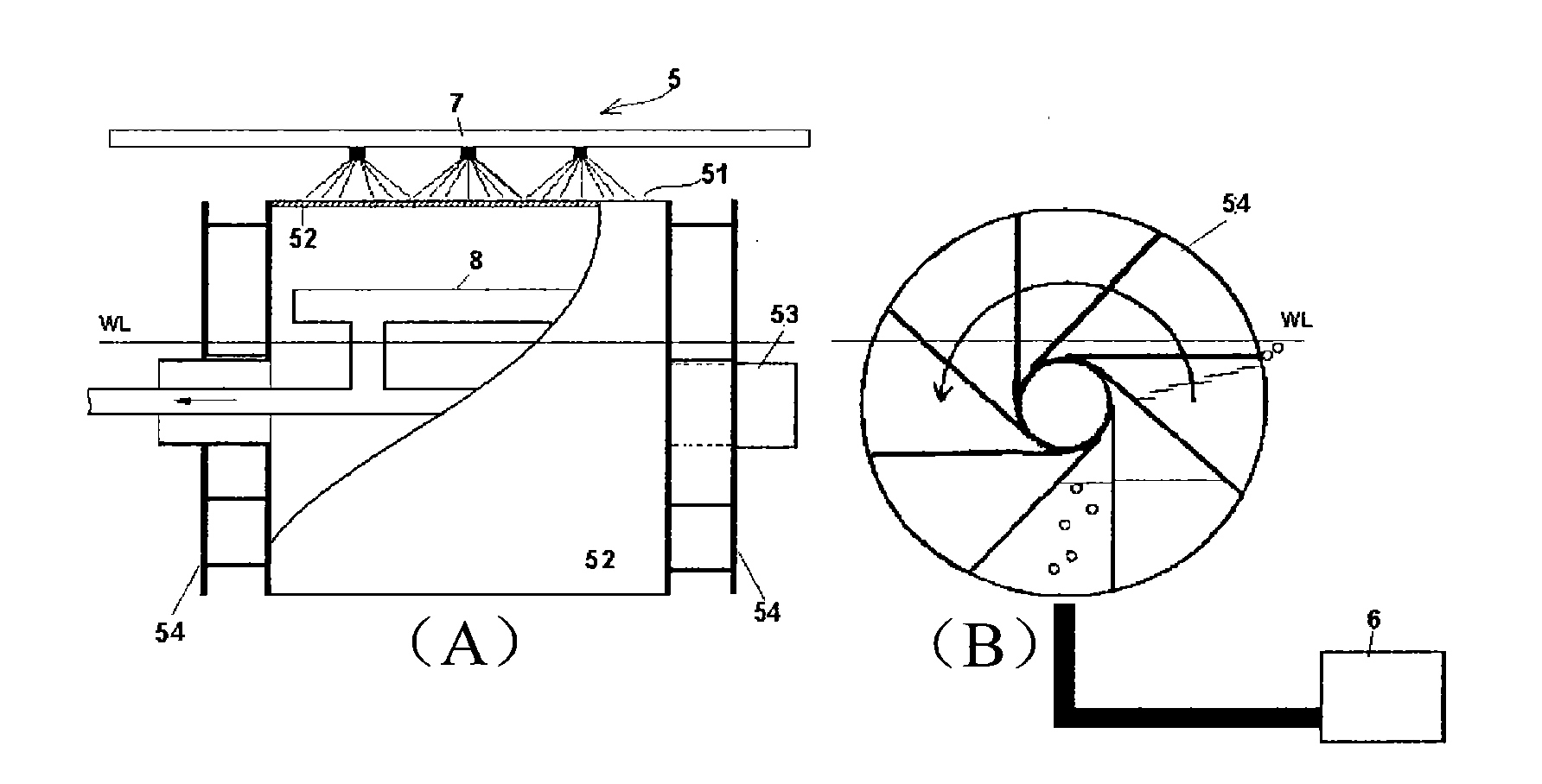
[0045] The filter mechanism includes a hollow cylinder with a filter membrane on its surface and an air wheel connected thereto, and is composed of a rotating cylindrical filter device horizontally supported at both ends by a cylindrical rotating shaft. This embodiment corresponds to the fourth aspect of the invention.

[0046] The hollow cylinder is soaked in clean water with only the upper part left, the air wheel receives air supplied from an external air source and rotates, and filtered raw water is supplied into the cylinder through the rotating shaft.

[0047] Because the hollow cylinder rotates slowly, it can be driven by a small amount of air. The hollow cylinder has a sufficiently large filtration membrane area relative to the amount of treated water, and the filtration is performed when water flows slowly from the inside of the filtration membrane to the outside. Because the pressure difference between the front and back of the filter membrane at this time is very s...


PUM


Abstract

To simultaneously achieve: (i) enabling migratory fish such as tuna to have safe and sufficient exercises without colliding the wall, (ii) allowing the coexistence of adult fish with juvenile fish and fry fish, (iii) largely saving the driving power of a pump for water purification, and (iv) laborsaving in washing and regenerating a filtration unit for removing waste materials. [MEANS FOR SOLVING PROBLEMS] A system for feeding migratory fish the inside of which is divided into a circular feeding tank (1) and a notched circular water-purification tank (3) in a circular shape with a missing and in which the feeding tank and the water-purification tank are located in close contact with each other like spectacles, characterized in that: the inside of the feeding tank is partitioned with a net sheet (16) into migration lanes for adult fish, juvenile fish and fry fish (11, 12, 13) respectively; circulation flows (14) in the same direction are flown in the individual lanes; the water-purification tank is provided with a filtration unit (5) and purified water having been filtered is stored therein; and these tanks (1, 3) are connected to each other via a water channel (15), by which the water in the feeding tank is supplied into the filtration unit due to the dynamic pressureof the circulation flows, and a circulation unit (4), by which the water in the water-purification tank is jetted into the feeding tank to form the circulation flows, and thus have substantially the same water levels.

Description

technical field [0001] The invention relates to a water tank for land culture of migratory fish. Background technique [0002] The applicant of the present invention discloses the invention related to the water tank for land aquaculture in Japanese Patent No. 3837709 (authorized on August 11, 2006). Afterwards, various beneficial opinions and ideas were obtained through the implementation of the patented invention, so a new patent application was filed for an improved invention with these contents added. [0003] Including the water tank related to the above-mentioned patent invention, in order to remove floating matter such as feed residue or feces in the breeding water tank, the water in the tank is generally pumped up with a water pump and transferred to the purification tank (or vice versa). However, such a breeding facility requires large power and piping for water supply. Furthermore, there is a problem that a large amount of labor is required to clean and recycle th...

Claims


Application Information

Patent Timeline
Patent Type & Authority Applications(China)
IPC IPC(8): A01K63/04A01K63/00
CPCA01K63/006A01K63/045A01K63/00A01K63/04A01K61/95B01D33/067B01D33/463B01D63/00B01D65/02
Inventor 鹫山一郎
Owner 鹫山 一郎
Why Eureka
Try Eureka