Thermostatic control valve

A thermostatic control valve and valve body technology, applied in the field of machinery, can solve the problems of cumbersome maintenance, complex system structure, inability to close the thermostatic control valve, etc. Effect

Inactive Publication Date: 2012-09-19
卓旦春
View PDF1 Cites 0 Cited by
  • Summary
  • Abstract
  • Description
  • Claims
  • Application Information

AI Technical Summary

Problems solved by technology

However, it must be used with an additional indoor temperature regulator, making the entire system complex and cumbersome to maintain
Moreover, it operates the thermostatic control valve through the indoor temperature. When the temperature of the fluid medium in the system suddenly rises, the thermostatic control valve cannot be closed immediately.

Method used


Image

  • Thermostatic control valve
  • Thermostatic control valve
  • Thermostatic control valve

Examples


Embodiment Construction

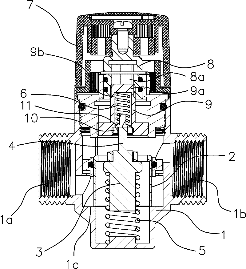
[0042] Such as figure 1 As shown, the thermostatic control valve includes a valve body 1 with a cavity inside, the two ends of the valve body 1 are the water inlet 1a and the water outlet 1b respectively, and the cavity between the water inlet 1a and the water outlet 1b is the fluid supply The water cavity through which the medium passes.

[0043] The spool 2 is set at the water cavity of the valve body 1 and can block the water cavity after it moves. There is also a thermal expansion device on the spool 2, and a spring is set between the spool 2 and the bottom of the valve body 1. a 5.

[0044] The thermal expansion device is composed of a thermal expansion sleeve 3 and a thermal expansion tube 4 arranged in the thermal expansion sleeve 3. The thermal expansion sleeve 3 is filled with a thermal expansion agent, and one end of the thermal expansion tube 4 is located in the thermal expansion sleeve 3. The thermal expansion tube 4. The other end stretches out the thermal expan...


PUM


Abstract

The invention provides a thermostatic control valve, and belongs to the machinery technical field, which solves the problems that the existing thermostatic control valve is in need of being matched with an indoor temperature regulator, thus causing the whole system to have complicated structure and trivial maintenance; and the thermostatic control valve can not be closed immediately when the temperature of a fluid medium in the system rises suddenly. The thermostatic control valve comprises a valve body with an internal cavity, wherein the valve body is internally equipped with a valve core capable of opening and closing the valve; the valve core is fixedly connected with a thermal expansion device; a spring 1 is arranged between the bottom of the valve body and the valve core; a thermal expansion tube in the thermal expansion device extends out of the valve core, and a spring 2 is arranged between the thermal expansion tube and the upper part of the valve body; the elastic force of the spring 1 is greater than that of the spring 2; and the valve core moves upwards under the action of the elastic force of the spring 1, so that a water inlet end and a water outlet end of the valve body are communicated together. The thermostatic control valve has the characteristics of simple structure, high stability and high practical value.

Description

technical field [0001] The invention belongs to the technical field of machinery and relates to a valve, in particular to a constant temperature control valve. Background technique [0002] The HVAC system is widely used in residential areas or high-rise buildings, and it implements household metering. Therefore, it is necessary for each user to save energy and use the HVAC system rationally. [0003] The thermostatic control valve is a kind of valve used to achieve the above purpose. Usually, each user in the system has an indoor temperature regulator and a thermostatic control valve. When the indoor temperature does not exceed the temperature set by the regulator, the thermostatic control valve is always disconnected, and the fluid medium with heat can flow smoothly. flow in the pipeline system of the user. Once the indoor temperature is higher than the temperature set by the regulator, the thermal expansion device in the thermostatic control valve moves the spool in th...

Claims


Application Information

Patent Timeline
Patent Type & Authority Patents(China)
IPC IPC(8): F16K17/36F16K31/70F16K31/60
Inventor 卓旦春
Owner 卓旦春
Why Eureka
Try Eureka