LED power control chip

A technology of LED power supply and control chip, which is applied in the field of chips to achieve the effects of improving safety protection, reducing costs and reducing costs

Inactive Publication Date: 2014-01-15
陈光德 +1
View PDF3 Cites 0 Cited by
  • Summary
  • Abstract
  • Description
  • Claims
  • Application Information

AI Technical Summary

Problems solved by technology

The invention solves the safety problem when the LED parallel branch circuit is broken, and solves the operation problem when the LED lamp needs timing and setting parameters. At the same time, the chip of the invention provides a programmable address and can be connected to the network under the control of a remote host. run

Method used


Image

  • LED power control chip
  • LED power control chip
  • LED power control chip

Examples


Embodiment Construction

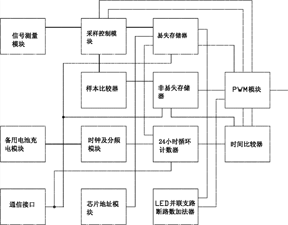
[0014] Referring to Fig. 1, the present invention includes a signal measurement module, a backup battery charging module, a communication interface, a sampling control module, a sample comparator, a clock and a frequency division module (that is, a clock generation module and a multi-channel frequency division module), a chip address module, an easy Lost memory, non-volatile memory, 24-hour cycle counter, LED parallel branch open circuit number adder, time comparator, PWM module. The connection relationship of each module is as follows:

[0015] 1) The signal measurement module is connected to the sampling control module to establish a sampling channel and obtain sampling data; the measured objects are ambient brightness signals, temperature signals and LED parallel branch circuit break signals input in the form of digital I / O for multiple channels , including two-channel resistance comparison method to measure temperature and ambient brightness, and a signal measurement...


PUM


Abstract

The invention relates to an LED power control chip. A signal measurement module is connected with a sampling control module; the sampling control module is respectively connected with a sample comparator, a volatile memory and a PWM (Pulse-Width Modulation) module; the sample comparator is connected with the volatile memory; the volatile memory is connected with the PWM module; a nonvolatile memory is connected with the PWM module; a 24-hour cycle counter is connected with a time comparator; the time comparator is connected with the nonvolatile memory and the PWM module; a clock frequency dividing module is connected with the 24-hour cycle counter; a chip address module is connected with the volatile memory; a communication interface is connected with the volatile memory; the communication interface is connected with the 24-hour cycle counter; the communication interface is connected with the nonvolatile memory; and an LED parallel branch opening summator is connected with the PWM module and the volatile memory. By using the LED power control chip, analog-to-digital conversion can be realized simply, and an analog circuit does not need to be embedded in the chip for minimizing the cost. The chip can be used separately, and also can be used in a networking way.

Description

technical field [0001] The invention relates to the technical field of chips, in particular to an LED power supply control chip. Background technique [0002] The driving of LED mainly adopts the constant current source controlled by PWM. The existing LED power supply control generally provides the temperature detection function, but the temperature compensation generally only controls the limit temperature, and the method of turning off the power supply or PWM without output is adopted. , for over-current protection, it only detects the total power supply current of the total constant current source to adjust the PWM output; it does not consider changing the given power output power through ambient light or condition parameters, because this is not called constant Current source; it does not consider the open circuit of the parallel branch of the LED. When the parallel branch of the LED is open, the current will be added to the remaining normal branch. In this way, the norm...

Claims


Application Information

Patent Timeline
Patent Type & Authority Patents(China)
IPC IPC(8): H05B37/02
CPCY02B20/42Y02B20/40
Inventor 陈光德倪端
Owner 陈光德
Why Eureka
Try Eureka