Transmission method and device of downlink data of advanced long term evolution system

A long-term evolution system and downlink data technology, applied in the field of downlink data transmission methods and devices, to achieve the effect of ensuring transmission performance

Active Publication Date: 2013-03-20
DATANG MOBILE COMM EQUIP CO LTD
View PDF4 Cites 0 Cited by
  • Summary
  • Abstract
  • Description
  • Claims
  • Application Information

AI Technical Summary

Problems solved by technology

[0005] The present invention provides an advanced downlink data transmission method in a long-term evolution system, which solves the problem of sending dedicated pilots for multi-stream transmission, and guarantees the transmission performance of special time slots as close as possible

Method used


Image

  • Transmission method and device of downlink data of advanced long term evolution system
  • Transmission method and device of downlink data of advanced long term evolution system
  • Transmission method and device of downlink data of advanced long term evolution system

Examples


Embodiment 1

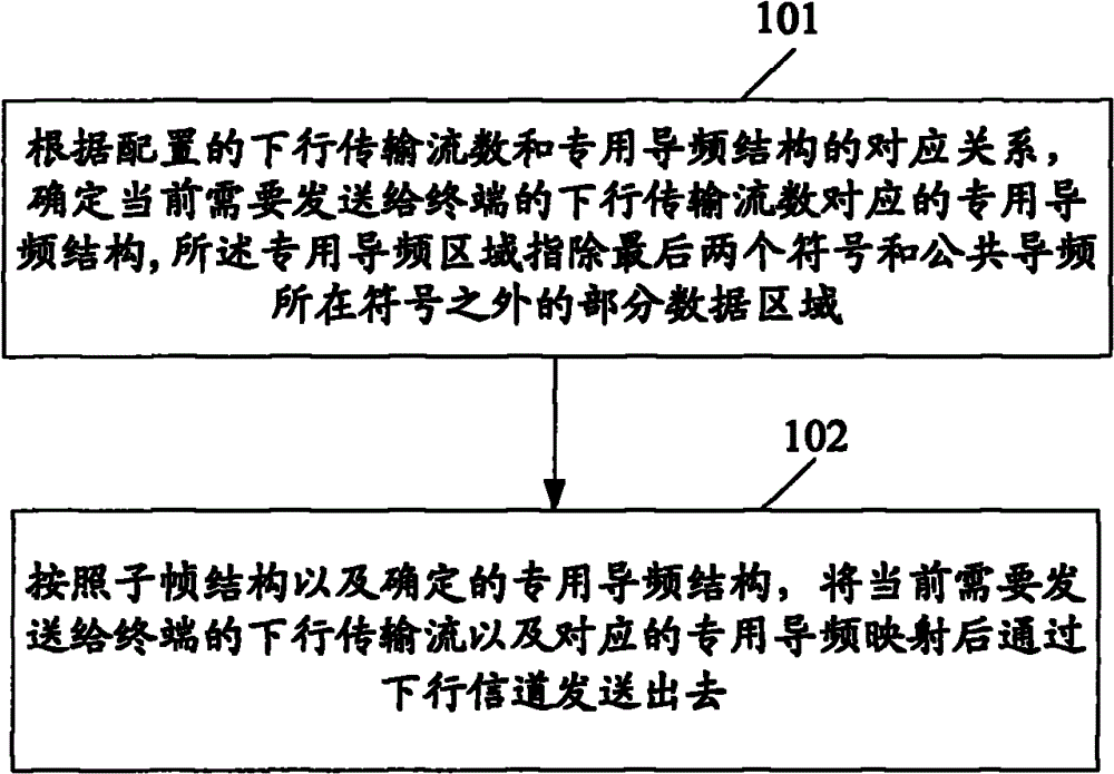
[0074] Embodiment 1 is the case of a dedicated pilot structure for 1-2 stream transmission:

[0075] Figure 3a , 3c , 3e, 3g, 3i and 3k are schematic diagrams of four dedicated pilot structures when the number of downlink transmission streams is 1 or 2 and the number of common pilots is 4 in the embodiment of the present invention; Figure 3b , 3d , 3f, 3h, 3j and 3l are schematic diagrams of four dedicated pilot structures when the number of downlink transmission streams is 1 or 2 and the number of common pilots is 2 in the embodiment of the present invention. Figure 3a-3l The pilot structure in the DWPTS domain can be used not only as a common pilot structure for common subframes and DWPTS domains, but also as a dedicated pilot structure for DWPTS domain. When DWPTS=3 symbols, no dedicated pilot is needed. When DWPTS=9, 10, 11, and 12symbols, one of the following dedicated pilot structures is adopted. If the symbol where the dedicated pilot is located is not in the DW...

Embodiment 2

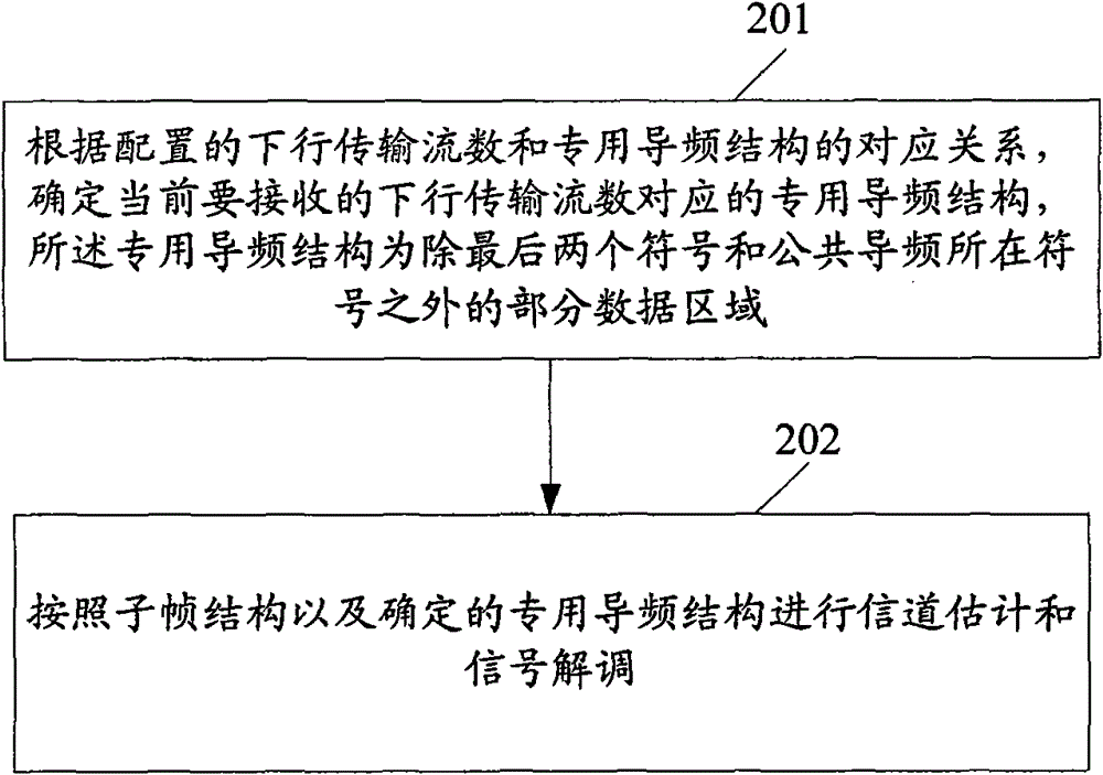
[0082] Embodiment 2: Dedicated pilot structure for 3-4 stream transmission

[0083] Figure 4a , 4c , 4e, 4g, 4i, 4k and 4m are schematic diagrams of four dedicated pilot structures when the number of downlink transmission streams is 3 or 4 and the number of common pilots is 4 in the embodiment of the present invention; Figure 4b , 4d , 4f, 4h, 4j, 4l and 4n are schematic diagrams of four dedicated pilot structures when the number of downlink transmission streams is 3 or 4 and the number of common pilots is 2 in the embodiment of the present invention. Figure 4a~4n The pilot structure in the DWPTS domain can be used not only as a common pilot structure for common subframes and DWPTS domains, but also as a dedicated pilot structure for DWPTS domain. DWPTS=3symbols, no dedicated pilot is required. DWPTS=9, 10, 11, 12symbols use a dedicated pilot structure as one of the following 4 types. If the symbol where the dedicated pilot is located is not in the DWPTS domain, this c...

Embodiment 3

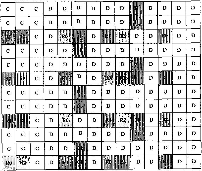
[0091] Embodiment 3: Dedicated pilot structure for 5-8 stream transmission.

[0092] Figure 5a , 5c , 5e, 5g, 5i, 5k, 5m, 5o, and 5q are schematic diagrams of nine dedicated pilot structures when the number of downlink transmission streams is 3 or 4 and the number of common pilots is 4 in the embodiment of the present invention; Figure 5b , 5d , 5f, 5h, 5j, 5l, 5n, 5p and 5r are schematic diagrams of nine dedicated pilot structures when the number of downlink transmission streams is 5-8 and the number of common pilots is 4 in the embodiment of the present invention. exist Figure 5a ~ Figure 5r Among them, the pilot structure can be used not only as a common pilot structure for common subframes and DWPTS domains, but also as a dedicated pilot structure for DWPTS domains. DWPTS=3symbols, no dedicated pilot is required. DWPTS=9, 10, 11, 12symbols use a dedicated pilot structure as one of the following. If the symbol where the dedicated pilot is located is not in the DWPT...


PUM


Abstract

The invention discloses a transmission method and device of the downlink data of an advanced long term evolution system, solving the problem of special pilot sending of one-stream or multi-stream transmission and ensuring the transmission performance of particular time slots as far as possible. The transmission method comprises the following steps of: determining a special pilot structure which corresponds to the number of downlink transmission steams needing to be currently sent to a terminal according to the corresponding relationship of configured downlink transmission steam number and the special pilot structure, wherein the special pilot structure comprises a special pilot area and the transmission mode information of special pilot in the special pilot area, wherein the special pilot area indicates an area of partial data except last two symbols and a symbol of common pilot; and mapping and then sending the downlink transmission steams needing to be currently sent to the terminal and the corresponding special pilot according to a subframe structure and the determined special pilot structure.

Description

technical field [0001] The present invention relates to the field of communication technology, in particular to a downlink data transmission method and device in an advanced long-term evolution system. Background technique [0002] The long-term advanced evolution (LTE-Advanced, LTE-A) standardization work is in progress, and in order to meet its peak rate requirements, 8X8 MIMO has become a key technology. In this case, it is necessary to configure the reference signals of the eight antenna ports respectively, so as to reduce the overhead introduced by the reference signals as much as possible while ensuring the system performance. In order to control the pilot overhead of the LTE-A system, the 3rd Generation Partnership Project (3rd Generation Partnership Project, 3GPP) meeting has decided to use dedicated pilots for demodulation and measurement pilots for measurement. [0003] Features of the dedicated pilot: (1) It is only sent on the physical resource block (Physical R...

Claims


Application Information

Patent Timeline
Patent Type & Authority Patents(China)
IPC IPC(8): H04L27/26H04L5/02
Inventor 徐婧沈祖康陆松鹤
Owner DATANG MOBILE COMM EQUIP CO LTD
Why Eureka
Try Eureka