
Wireless monitoring system and communication method thereof

A wireless monitoring and communication method technology, applied in wireless communication, closed-circuit television system, wireless network protocol, etc., can solve the problems of inability to obtain high uplink transmission rate of wireless monitoring system, waste of downlink resources, etc., and achieve high uplink rate and high service. quality effect

Inactive Publication Date: 2011-03-30
LEADCORE TECH
View PDF2 Cites 11 Cited by
  • Summary
  • Abstract
  • Description
  • Claims
  • Application Information

AI Technical Summary

Problems solved by technology

It can be seen that in the case of directly applying the existing TD-LTE system frame structure, the downlink resources are greatly wasted, and at the same time, the high uplink transmission rate required by the wireless monitoring system cannot be obtained.

Method used


Image

  • Wireless monitoring system and communication method thereof
  • Wireless monitoring system and communication method thereof
  • Wireless monitoring system and communication method thereof

Examples


Embodiment Construction

[0029] Embodiments of the present invention will now be described in detail with reference to the accompanying drawings.

[0030] According to one embodiment, the wireless monitoring system of the present invention is based on TD-LTE technology, wherein the first communication device in the wireless monitoring system sends wireless frames to the second communication device, and the communication method of the present invention increases by changing the frame structure of the wireless frame The frame structure has a maximum configuration ratio of uplink and downlink, thereby increasing the uplink transmission rate.

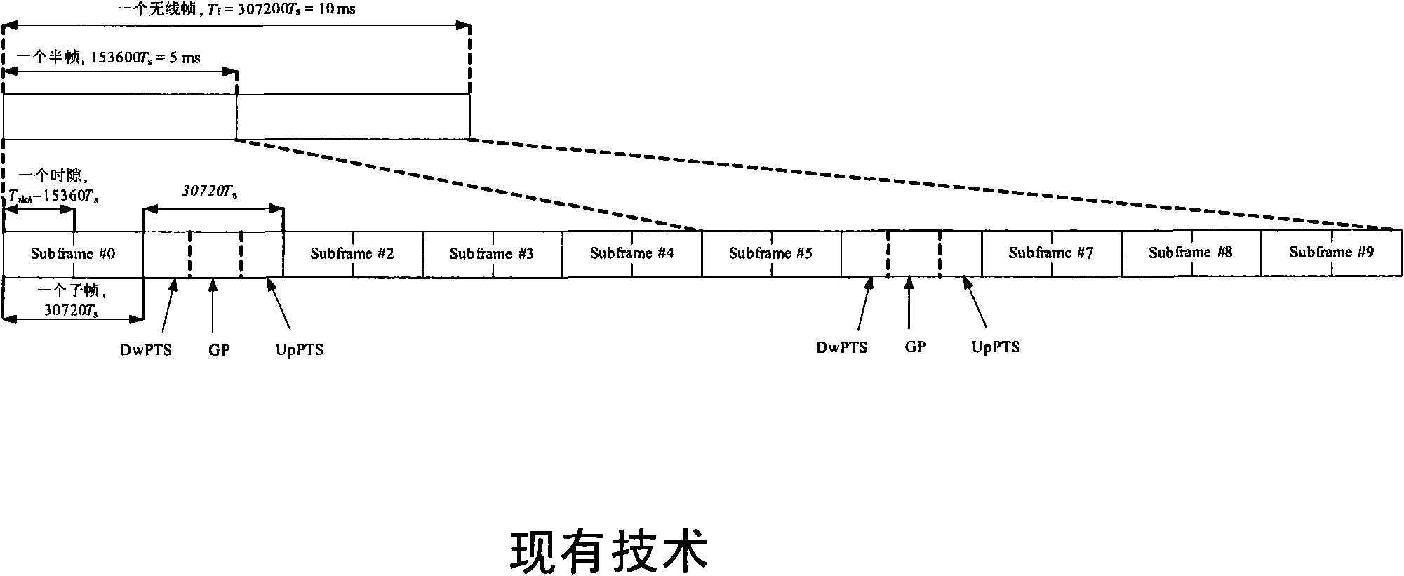
[0031] For example, figure 2 Shows the traditional TD-LTE frame structure, where a radio frame length (T f =307200·T s = 10ms) contains two half-frames (153600·T s =5ms), each half frame contains 5 subframes (30720·T s =1ms), and each subframe contains two slots (T slot =15360·T s = 0.5ms).

[0032] corresponds to figure 2 , image 3 It schematically sho...


PUM


Abstract

The invention provides a communication method for a wireless monitoring system. The communication in the wireless monitoring system is based on TD-LTE (time division-long term evolution) technology. The communication method comprises that: a first communication device in the wireless monitoring system sends a wireless frame to a second communication device in the wireless monitoring system, wherein the uplink and downlink maximum configuration ratio of the frame structure is increased by changing the frame structure of the wireless frame so as to improve the uplink transmission ratio. The communication method can improve the uplink rate by at least 25 percent without increasing the complexity of the system to acquire higher QoS (quality of service) and shorter time delay.

Description

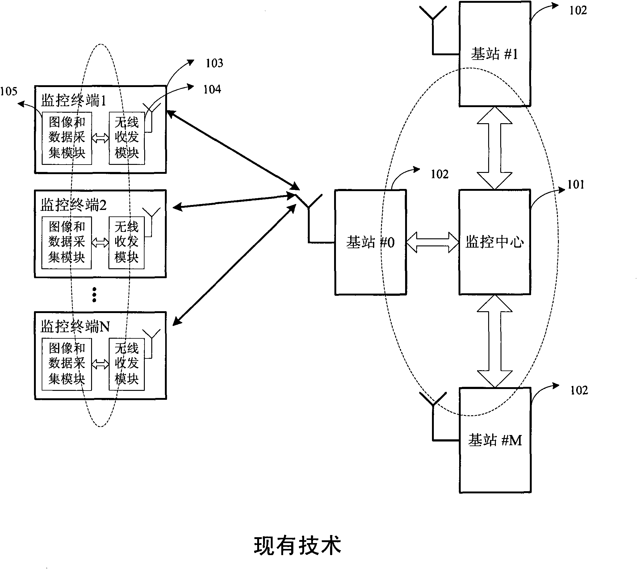
technical field [0001] The present invention relates to a wireless monitoring technology, in particular to a wireless monitoring system and a communication method thereof. The wireless monitoring system is, for example, a wireless monitoring system based on TD-LTE (Long Term Evolution) technology. Background technique [0002] figure 1 The basic architecture of the current wireless monitoring system is shown. Such as figure 1 As shown, the wireless monitoring system at least includes a monitoring center 101, several base stations 102 (such as figure 1 base stations #0~#M) and several monitoring terminals 103 (such as figure 1 The monitoring terminals 1~N in). In particular, the monitoring terminal 103 may be composed of a wireless transceiver module 104 and an image and data collection module 105 that communicate with each other. [0003] The base station 102 and the monitoring terminal 103 form a cellular wireless access network. On the one hand, the base station 102 ...

Claims


Application Information

Patent Timeline
Patent Type & Authority Applications(China)
IPC IPC(8): H04W80/02H04N7/18
Inventor 陆迎光
Owner LEADCORE TECH
Learn More