Positioning device

A technology of positioning device and positioning part, applied in positioning device, lifting device, clamping and other directions, can solve the problems of broken tool, inconvenient processing of boom frame, large structure of boom frame, etc., to achieve convenient alignment and quick adjustment convenient effect

Active Publication Date: 2011-04-06
ZOOMLION HEAVY IND CO LTD
View PDF7 Cites 11 Cited by
  • Summary
  • Abstract
  • Description
  • Claims
  • Application Information

AI Technical Summary

Problems solved by technology

The chords of the crawler crane jib are all made of seamless steel pipes, most of which are variable cross-sections. It is not easy to position and clamp during the overall metal processing, and the workpiece shakes seriously, so that the double-sided boring equipment cannot perform double-sided boring and simultaneously process both sides. However, it can only be processed on one side, and the selected spindle speed is low and the amount of feed is small. Otherwise, the workpiece will vibrate seriously and the tool will be damaged, resulting in low metal processing efficiency and processing quality.
[0004] The known structure for metal processing and positioning of the boom frame is to support the boom frame to be processed with a screw rod, and the lower ends of each chord of the boom frame are positioned with a screw rod, which is a point contact. This kind of screw rod positioning can only Positioning the height direction, but there is no limit to the vibration of the jib chord in the lateral direction. Therefore, when the jib is proc

Method used


Image

  • Positioning device
  • Positioning device
  • Positioning device

Examples


Example Embodiment

[0023] Hereinafter, the present invention will be described in detail with reference to the accompanying drawings and the embodiments.

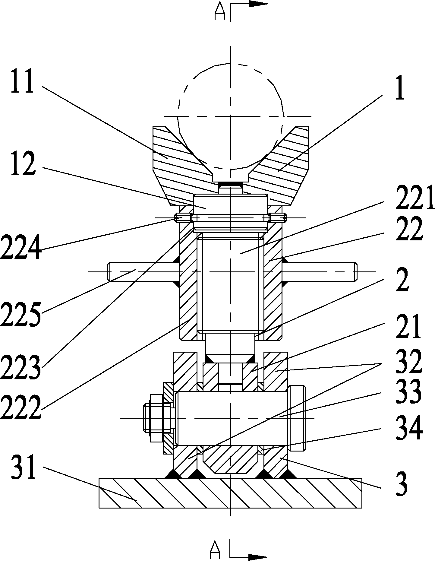
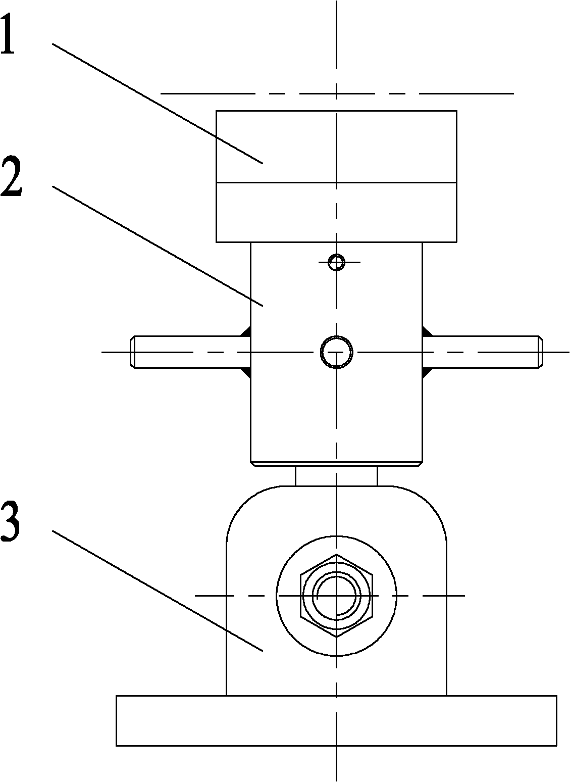
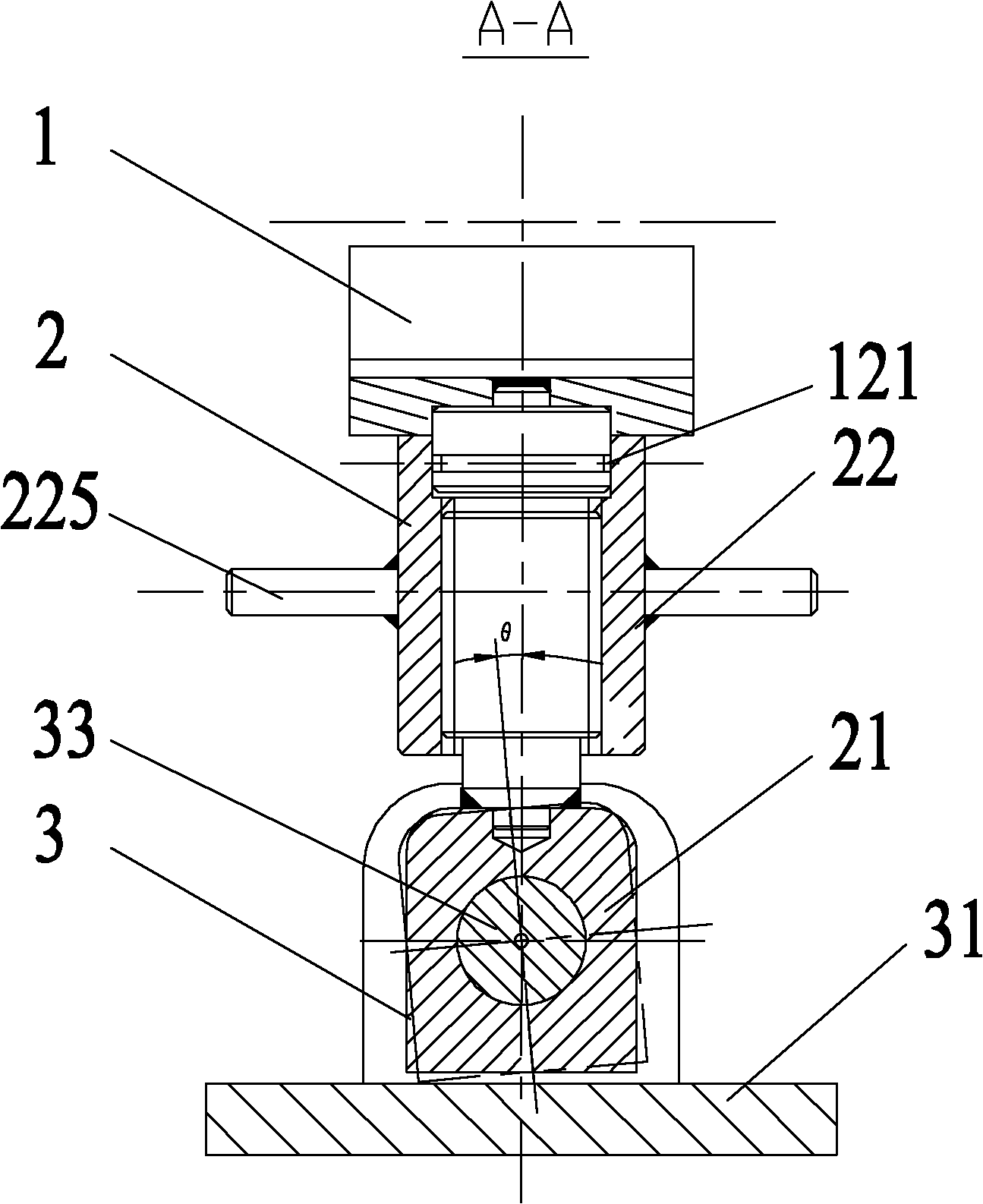
[0024] Such as figure 1 , figure 2 , image 3 As shown, the embodiment of the positioning device according to the present invention includes a base part 3, which has a structure supported on a working surface, and a positioning part 1, which is arranged on the base part 3 and has a structure for clamping the object to be processed; The base part 3 includes a rotating shaft 33, the rotating shaft 33 is horizontally arranged on the base part 3, and the positioning part 1 is rotatably arranged on the rotating shaft 33. The base part 3 also includes: a base 31, which is stably arranged on the working surface of the positioning device; a rotating shaft support 32, which includes two oppositely arranged supporting plates fixed on the base 31, and the supporting plates are vertically arranged on the base 31, Each support plate is provided with a rotat...


PUM


Abstract

The invention provides a positioning device which comprises a base part (3) and a positioning part (1), wherein the positioning part (1) is arranged on the base part (3); the base part (3) comprises a rotating shaft (33) which is horizontally arranged on the base part (3); and the positioning part (1) is rotatablely arranged around the rotating shaft (33). When the positioning device is used for positioning a boom stand, the inclination angle of the positioning part can be automatically adjusted according to the inclination angle of the boom stand, so that the positioning part and the boom stand have a larger contact area, thereby forming a more stable positioning structure for the boom stand.

Description

technical field [0001] The invention relates to the field of machining positioning, and more specifically, to a positioning device. Background technique [0002] Crawler crane is a new type of crane product introduced in China in recent years. It is widely used, has great market demand and high product added value. But the current domestic manufacturing process is still very rough, there is a lot of room for improvement and development. [0003] The crawler crane jib is generally a tubular truss arm structure, with many holes on the top and bottom jibs, high machining accuracy, and high coaxiality requirements. Therefore, it is necessary to carry out integral metal processing on CNC double-sided boring or pentahedron. The chords of the crawler crane jib are all made of seamless steel pipes, most of which are variable cross-sections. It is not easy to position and clamp during the overall metal processing, and the workpiece shakes seriously, so that the double-sided boring e...

Claims


Application Information

Patent Timeline
IPC IPC(8): B23Q3/00
CPCB66C23/82B66F13/00
Inventor 詹纯新刘权张红霞易伟平黄建军
Owner ZOOMLION HEAVY IND CO LTD
Why Eureka
Try Eureka