Electric brush keeping device for a motor

A technology for holding devices and motors, applied in the direction of electromechanical devices, electric components, electrical components, etc., to achieve miniaturization, mechanical strength, and height reduction

Inactive Publication Date: 2011-04-06
KOKUSAN DENKI CO LTD
View PDF7 Cites 2 Cited by
  • Summary
  • Abstract
  • Description
  • Claims
  • Application Information

AI Technical Summary

Problems solved by technology

In addition, since the brush is manufactured by sintering after being shaped using a forming die, it is not easy to form the protruding portions 6a, 6a on the side thereof.

Method used


Image

  • Electric brush keeping device for a motor
  • Electric brush keeping device for a motor
  • Electric brush keeping device for a motor

Examples


Embodiment Construction

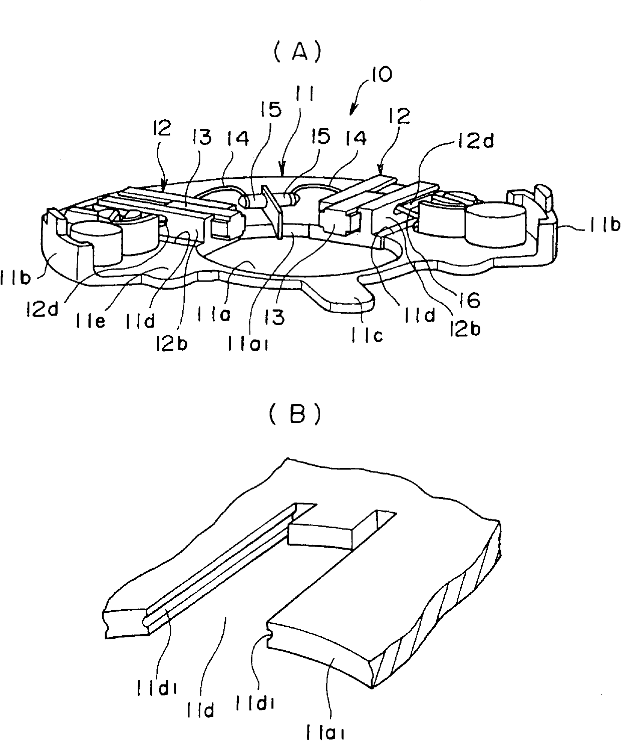
[0031] figure 1 A is a perspective view showing an embodiment of the present invention. The illustrated brush holding device 10 includes a brush holding plate 11 , a pair of brush holders 12 , 12 fixed to the brush holding plate 11 , and brushes 13 , 13 respectively held by the pair of brush holders 12 , 12 .

[0032] The brush holding plate 11 is produced by molding an insulating resin. The brush holding plate 11 has a commutator ( figure 1 A. figure 1 B (not shown) through the opening 11a. A pair of upright wall portions 11b, 11b are formed at symmetrical positions separated by 180° on the outer peripheral portion of the brush holding plate 11, and a tongue-shaped protruding portion 11c is formed between the upright wall portions 11b, 11b.

[0033] In the brush holding plate 11 , the central axis of the opening 11 a is arranged so as to coincide with the central axis of the not-shown commutator. A pair of substantially U-shaped notches 11 d extending in the radial di...


PUM


Abstract

The invention provides an electric brush keeping device for keeping the electric brush of a motor, comprising an electric brush keeping plate with a notch; an electric brush bracket with a substrate and a pair of wall parts projecting from the surface of the substrate, wherein the substrate is combined with the electric brush keeping plate by being embedded with the notch of the electric brush keeping plate and the surface of the substrate of the electric brush bracket and the surface of the electric brush keeping plate are on the same surface and the electric brush is inserted into the pair of the wall parts of the electric brush bracket. The height of the wall parts of the electric brush bracket is set equal to that of the electric brush inserted into the space between two wall parts and a projection part formed on the front end of the wall parts of the electric brush bracket is fastened with the angle part of the electric brush, so as to prevent the electric brush from being disengaged with the wall parts.

Description

technical field [0001] This invention relates to a brush holder for a DC motor with brushes. Background technique [0002] A DC motor including a commutator and brushes in contact with the commutator includes a brush holding device for holding the brushes in contact with the commutator on the stator side. Figure 6 (A) shows the brush holder 1 shown in (Japanese) Utility Laid-Open No. 2-3169 as an example. This brush holding device includes: a brush holding plate 2 having an opening 201 for passing through a commutator attached to a rotor of a motor; and a brush holder 3 fixed to the brush holding plate 2 . The brush holding plate 2 is arranged such that the central axis of the opening 201 coincides with the central axis of the not-shown commutator (the central axis of the rotor). The brush holder 3 has a hollow portion 301 having a rectangular cross section, and an opening 301 a at one end in the longitudinal direction of the hollow portion 301 is opened on the central ax...

Claims


Application Information

Patent Timeline
Patent Type & Authority Applications(China)
IPC IPC(8): H02K5/14
Inventor 江口明彦
Owner KOKUSAN DENKI CO LTD
Why Eureka
Try Eureka