Joint tracking detection system for cameras

A tracking detection and camera technology, which is applied in the field of joint tracking and detection systems using multiple PTZ cameras, can solve the problems of limited monitoring range and the inability of the monitoring system to realize joint continuous tracking and detection, and meet real-time requirements, high processing speed, and improved Tracking the Effects of Efficiency

Active Publication Date: 2011-04-06
WUXI ZGMICRO ELECTRONICS CO LTD
View PDF3 Cites 39 Cited by
  • Summary
  • Abstract
  • Description
  • Claims
  • Application Information

AI Technical Summary

Problems solved by technology

But in the current monitoring field, usually a camera is only responsible for the area it monitors. Although each PTZ camera can move, the monitoring range is still limited. When a moving target leaves the monitoring range of one PTZ and enters another When the monitoring range of PTZ is limited, the existing monitoring system cannot realize joint continuous tracking and detection

Method used


Image

  • Joint tracking detection system for cameras
  • Joint tracking detection system for cameras
  • Joint tracking detection system for cameras

Examples


Embodiment Construction

[0036] Reference herein to "one embodiment" or "an embodiment" refers to a particular feature, structure or characteristic that can be included in at least one implementation of the present invention. "In one embodiment" appearing in different places in this specification does not all refer to the same embodiment, nor is it a separate or selective embodiment that is mutually exclusive with other embodiments.

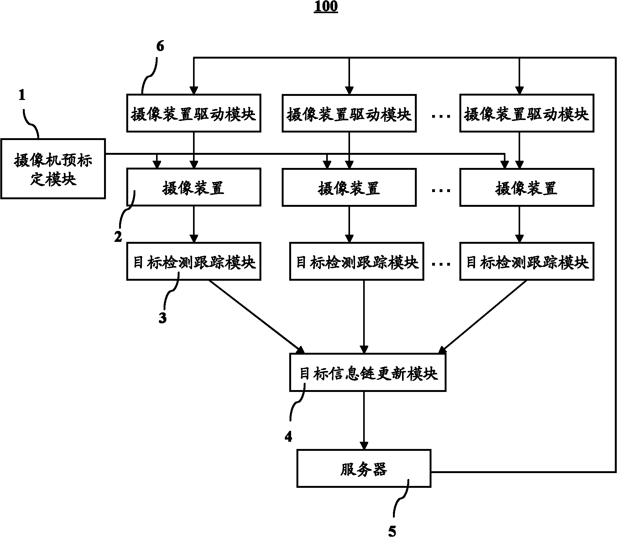
[0037] see figure 1 As shown, it shows a structural block diagram of the multi-camera joint tracking and detection system 100 of the present invention. As shown in the figure, the multi-camera joint tracking and detection system 100 of the present invention includes: a camera pre-calibration module 1, several camera devices 2, a target detection and tracking module 3, a target information chain update module 4, a server 5 and a camera driver Module 6.

[0038] The camera pre-calibration module 1 is used to calibrate each camera device 2 (camera). According to the camer...


PUM


Abstract

The invention provides a joint tracking detection system for a plurality of PTZ (Pan / Tilt / Zoom) cameras, comprising a plurality of PTZ cameras, a camera pre-calibration module, a PTZ drive module, a target detection and tracking module, a target information chain update module and a server. The camera pre-calibration module is used for pre-calibrating the plurality of cameras, the target detection and tracking module is used for detecting and tracking a target and sending tracked information to the server through the target information chain update module, and the server informs the PTZ drivemodule to adjust the parameters of the PTZ cameras to continuously track the target.

Description

【Technical field】 [0001] The invention relates to the monitoring field, in particular to a joint tracking and detection system utilizing multiple PTZ cameras. 【Background technique】 [0002] Pan, Tilt, Zoom (PTZ for short) cameras have been more and more widely used because of their variable viewing angle and zoom capabilities. But in the current monitoring field, usually a camera is only responsible for the area it monitors. Although each PTZ camera can move, the monitoring range is still limited. When a moving target leaves the monitoring range of one PTZ and enters another When the monitoring range of PTZ is limited, the existing monitoring system cannot realize joint continuous tracking and detection. 【Content of invention】 [0003] The purpose of the present invention is to provide a multi-camera joint tracking and detection system. [0004] In order to achieve the aforementioned purpose, the present invention provides a camera joint tracking and detection system, w...

Claims


Application Information

Patent Timeline
Patent Type & Authority Applications(China)
IPC IPC(8): H04N7/18G06T7/00G06T7/20
Inventor 卢晓鹏
Owner WUXI ZGMICRO ELECTRONICS CO LTD
Why Eureka
Try Eureka