Buffer management for communication systems

a communication system and buffer management technology, applied in the field of data communication, can solve the problems of data loss, buffer management system throughput reduction, data loss,

Inactive Publication Date: 2002-11-28
ISHONI NETWORKS
View PDF7 Cites 101 Cited by
  • Summary
  • Abstract
  • Description
  • Claims
  • Application Information

AI Technical Summary

Benefits of technology

[0011] Embodiments of the system are directed to managing data buffers such that communication packets stored in the buffers are efficiently processed, segmented, reassembled, and forwarded to appropriate network destinations. In one or more embodiments, the system includes one or more queues that are used to reference and store information associated with the communication packets. Each queue may be implemented either as on-chip memory or in external memory. In certain embodiments, the queues are implemented as a combination of the two. Due to the overhead associated with managing data transfer to and from external memory, storing and accessing data in on-chip memory is faster than storing or accessing data in external memory. Unfortunately, because on-chip memory is expensive to manufacture in comparison with external memory, to save costs, it is desirable to limit the size of on-chip memory to a minimum.
[0015] The CPU receives an interrupt to read RRQ when RRQ is not empty. CPU reads a BD and based on information stored therein determines whether a communication packet associated with the BD is to be transmitted to a different I / O port. Handling data packets through the associated BDs speeds up packet processing in that the CPU avoids the resource consuming process of accessing the external memory to retrieve needed data. All processing related data is included in BDs stored in RRQ implemented in on-chip memory.
[0017] In embodiments of the system, data buffer queues have configurable minimum and maximum thresholds. These thresholds are used to monitor and maintain an optimal storage level in the queue. For example, when a maximum threshold is reached, data pointers or BDs stored in the queues are transferred to separate queues in external memory. When a minimum threshold is reached, data pointers or BDs stored in external memory, if any, are transferred to corresponding queues. For example, data pointers transferred to external memory from a WFQ associated with one I / O are returned to that I / O's RFQ. The expansion of data pointers and BDs to external memory allows the buffer manager to handle high traffic communication without substantially compromising processing speed or throughput.

Problems solved by technology

Due to high costs and overhead associated with manufacturing small size on-chip memory, the on-chip memory implemented in a buffer management system needs to be limited to a reasonable size.
As such, this size limitation may result in data loss and can substantially reduce the throughput of the buffer management system.
However, in many instances, the communication system may not be fast enough to process packets as quickly as they arrive.
Due to the overhead associated with managing data transfer to and from external memory, storing and accessing data in on-chip memory is faster than storing or accessing data in external memory.
Unfortunately, because on-chip memory is expensive to manufacture in comparison with external memory, to save costs, it is desirable to limit the size of on-chip memory to a minimum.
In a high traffic communication system, however, this size limitation may adversely effect the speed at which communication packets can be processed.
If a queue implemented in on-chip memory and used for storing received communication packets is full, then the system will not be able to receive any more packets until the information currently stored in the on-chip queue are processed.
This inability to support newly arriving communication packets can lead to communication packets being dropped, and slow down the communication speed.
Directly handling data stored in a data buffer is relatively slow because the data is stored in external memory.
Unfortunately, due to its relatively expensive cost, on-chip memory is not an economically viable medium for storage of large volumes of data.
If the newly calculated remainder value does not match the transmitted remainder, an error is detected that indicates data was corrupted during transmission.
Frequent DMA transfers between on-chip and external memory are resource intensive.

Method used


Image

  • Buffer management for communication systems
  • Buffer management for communication systems
  • Buffer management for communication systems

Examples


Embodiment Construction

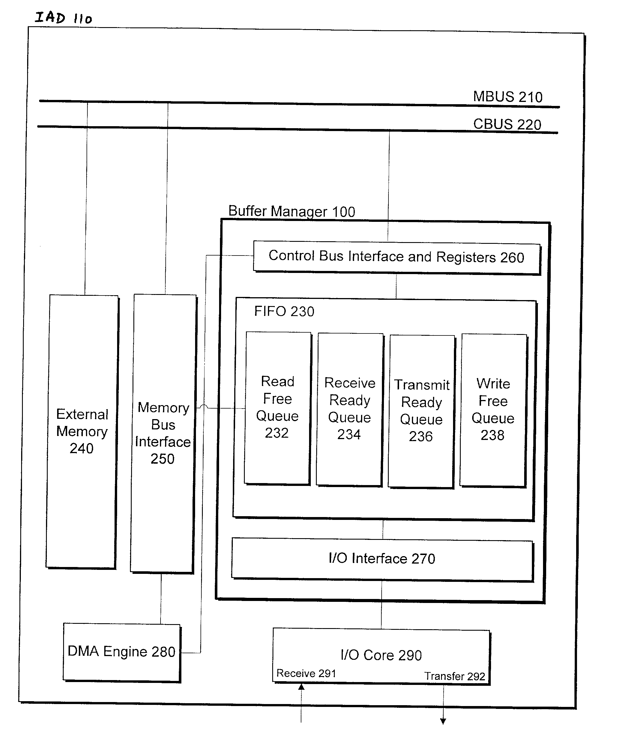
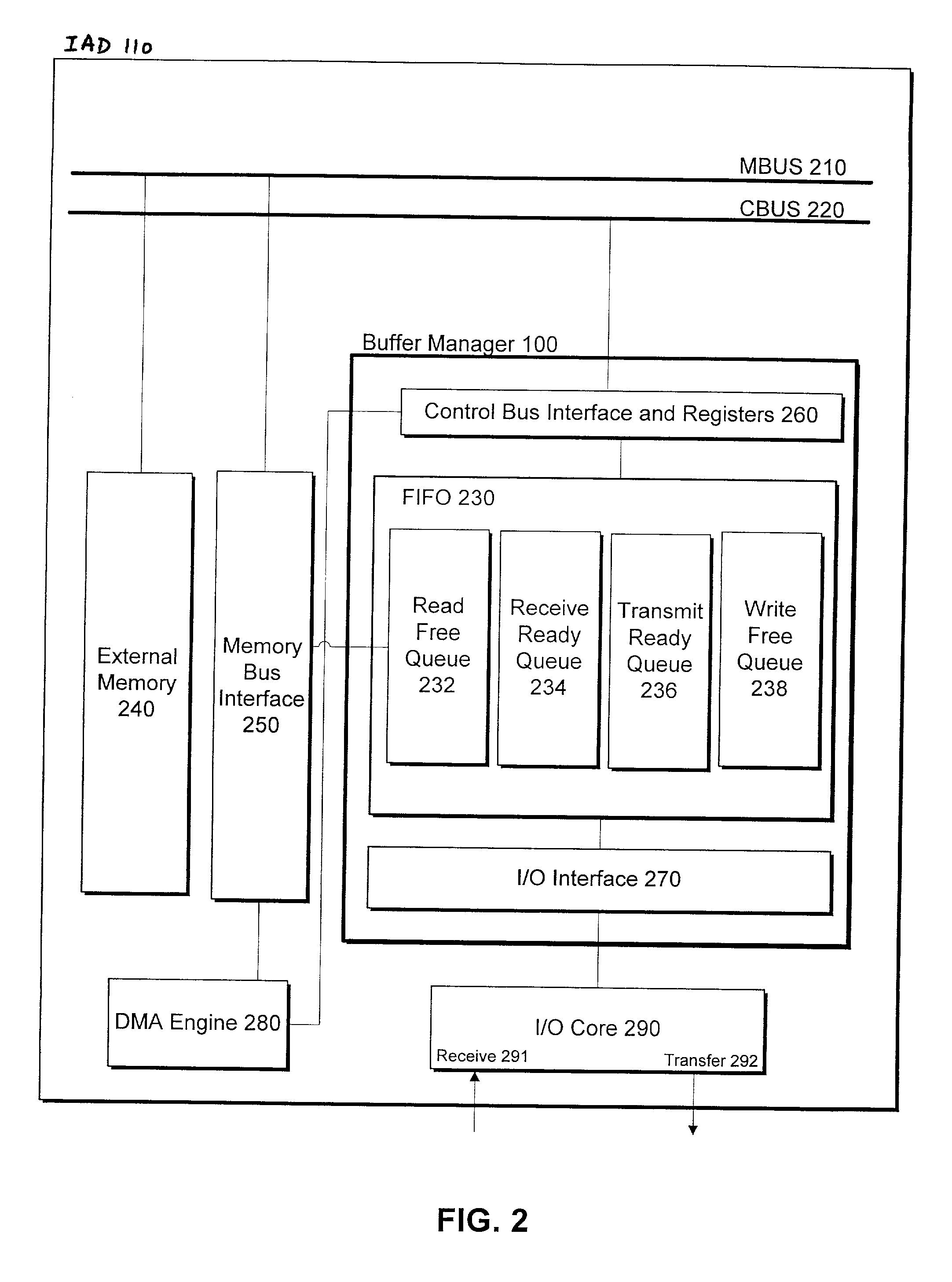
BUFFER MANAGER INTERFACE

[0135] CBUS Interface and Registers

[0136] In certain embodiments of the invention, CBUS interface is shared with the I / O core interface. Table A1 provides a description of I / O signals between the CBUS interface and I / O core 290.

7TABLE A1 CBUS interface signals between I / O core module Number Signal I / O Description 1 CbusAD_BM[31:0] Input CBUS Address / Data bus to register 2 Cbus_valid Input CBUS command valid 3 CbusWr_NotRd Input CBUS write / read 1: write mode 0: read mode 4 BM_Rdata[31:0] Output Register data return to CBUS.

[0137] Table A2 provides a summary of registers included in CBUS interface and registers 260.

8TABLE A2 Register summary Address offset Register Description 0 Threshold register 1 1 Threshold register 2 2 Threshold register 3 3 Data buffer base address 4 Interrupt status 5 Interrupt enable 6 Control 7 RFQ 8 RRQ 9 TRQ 1 10 TRQ 2 11 TRQ 3 12 TRQ 4 13 WFQ 14 DMA command 15 BRQ expansion counters 16 TRQ 1 expansion counters 17 TRQ 2 expansion cou...


PUM


Abstract

Methods and systems for managing data packets in various communication networks are provided. The system includes a first memory for storing at least a free data pointer and a buffer descriptor. The free data pointer points to a data buffer allocated in a second memory. The buffer descriptor includes at least a data pointer pointing to a data buffer configured to store one or a portion of the communication packet. The first memory has a maximum threshold such that if the number of buffer descriptors stored in the first memory reaches the maximum threshold one or more buffer descriptors stored in the first memory are transferred to the second memory.

Description

[0001] 1. Field of Invention[0002] The present invention relates to data communications and, more particularly, to a method and system for managing data buffers in a communication system to promote communication among multiple networks.COPYRIGHT AND TRADEMARK NOTICE[0003] A portion of the disclosure of this patent document may contain material that is subject to copyright protection. The owner has no objection to the facsimile reproduction by any one of the patent document or the patent disclosure, as it appears in the Patent and Trademark Office patent file or records, but otherwise reserves all copyrights whatsoever.[0004] Certain marks referenced herein may be common law or registered trademarks of third parties affiliated or unaffiliated with the applicant or the assignee. Use of these marks is for the purpose of providing an enabling disclosure by way of example and shall not be construed to limit the scope of this invention to items or services associated with such marks.RELAT...

Claims


Application Information

Patent Timeline
Patent Type & Authority Applications(United States)
IPC IPC(8): H04L12/56
CPCH04L49/90H04L49/9078H04L49/9047H04L49/901
Inventor SANGHA, ONKAR S.KWON, EDMAHESHWARI, VIJAYKUICHI, AKIHIRO
Owner ISHONI NETWORKS
Why Eureka
Try Eureka