A centrifugal separator

A centrifugal separator and separation chamber technology, applied in centrifuges, centrifuges with rotating drums, etc., can solve problems such as energy loss

Inactive Publication Date: 2012-11-28
ALFA LAVAL CORP AB
View PDF3 Cites 0 Cited by
  • Summary
  • Abstract
  • Description
  • Claims
  • Application Information

AI Technical Summary

Problems solved by technology

Material is thus discharged from the drum close to the perimeter causing huge energy losses

Method used


Image

  • A centrifugal separator
  • A centrifugal separator
  • A centrifugal separator

Examples


Embodiment Construction

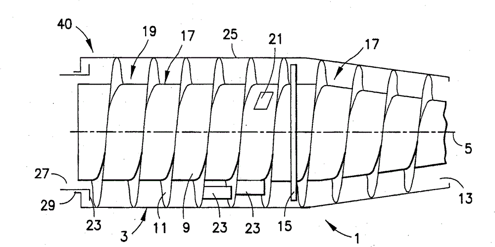
[0028] figure 1 A centrifugal separator or centrifuge 1 in which the invention can be applied is schematically shown. The centrifuge 1 comprises a drum or drum 3 which rotates during operation about a longitudinal axis of rotation 5 extending in the longitudinal direction of the drum. In the drum 3 is arranged a screw conveyor 7 comprising an elongated body 9 carrying a worm 11 for transporting the solid phase of the material separated in the centrifuge towards a solid phase outlet 13 . A partition 15 divides the interior of the drum 3 into a solid phase outlet segment 17 and a separation chamber 19 . The elongated body 9 includes an inlet 21 for the material to be separated by the centrifuge. A barrier plate 23 is provided in the separation chamber 19 to enable separation of the liquid phase of the material in the separation chamber 19 into a light liquid phase and a heavy liquid phase. Due to the different densities, the heavy liquid phase will be placed closer to the cir...


PUM


Abstract

The centrifugal separator (1) comprises a bowl (3) rotating during operation in a direction of rotation (65) and having a separation chamber (19). A base (131) is provided at a rear longitudinal end of the bowl (3) to define the separation chamber (19). The base (131) comprises a first outlet opening (45) defined in the radial direction at a first level (67) by a weir (43), and the base (131) defines a rear longitudinal area (41) of the centrifugal separator (1). An outlet chamber (37) communicates with the separation chamber (19) through the first outlet opening (45). The outlet chamber (37)is connected with an outlet chamber outlet opening (148), which is opening at a second level (69) below the first level (67) into an exterior (40) of the bowl (3) in a second longitudinal area (50) in front of the rear longitudinal area (41). The outlet chamber outlet opening (148) is provided with an outlet nozzle (59) with an outlet direction opposite the direction of rotation (65), and an overflow inlet opening (55) is present in the outlet chamber (37), which overflow inlet opening (55) is placed at a third level (71) between the first and the second level (67 and 69), and the overflow inlet opening (55) communicates with an overflow outlet opening (57), which is opening into the exterior (40) of the bowl (3) in the second longitudinal area (50).

Description

technical field [0001] The present invention relates to a centrifugal separator comprising: a bowl rotating during operation in a rotational direction about an axis of rotation extending in the longitudinal direction of the bowl, the radial direction extending perpendicular to the longitudinal direction; A separation chamber in the drum; a base disposed at the rear longitudinal end of the drum to define the separation chamber, said base comprising a first outlet opening defined at a first level in a radial direction by a weir (weir), and the The base defines a rear longitudinal region of the centrifugal separator; an outlet chamber communicating with the separation chamber through a first outlet opening; the outlet chamber is connected to an outlet opening of the outlet chamber, and the outlet chamber outlet opening is communicated at a second level below the first level; Towards the outside of the drum in the second longitudinal region forward of the rear longitudinal region....

Claims


Application Information

Patent Timeline
Patent Type & Authority Patents(China)
IPC IPC(8): B04B1/10B04B1/20
CPCB04B1/20B04B2001/2075B04B2001/2083
Inventor B·马德森
Owner ALFA LAVAL CORP AB
Why Eureka
Try Eureka