Endoscope

A technology of endoscope and insertion part, applied in the field of endoscope, can solve the problem of easy accumulation of heat and the like

Active Publication Date: 2018-03-16
FUJIFILM CORP
View PDF9 Cites 0 Cited by
  • Summary
  • Abstract
  • Description
  • Claims
  • Application Information

AI Technical Summary

Problems solved by technology

However, heat generated in solid-state imaging elements and the like tends to accumulate in a small space that is closely arranged, so it is necessary to prepare a heat dissipation path

Method used


Image

  • Endoscope
  • Endoscope
  • Endoscope

Examples


Embodiment Construction

[0027] Hereinafter, embodiments of the present invention will be described with reference to the drawings.

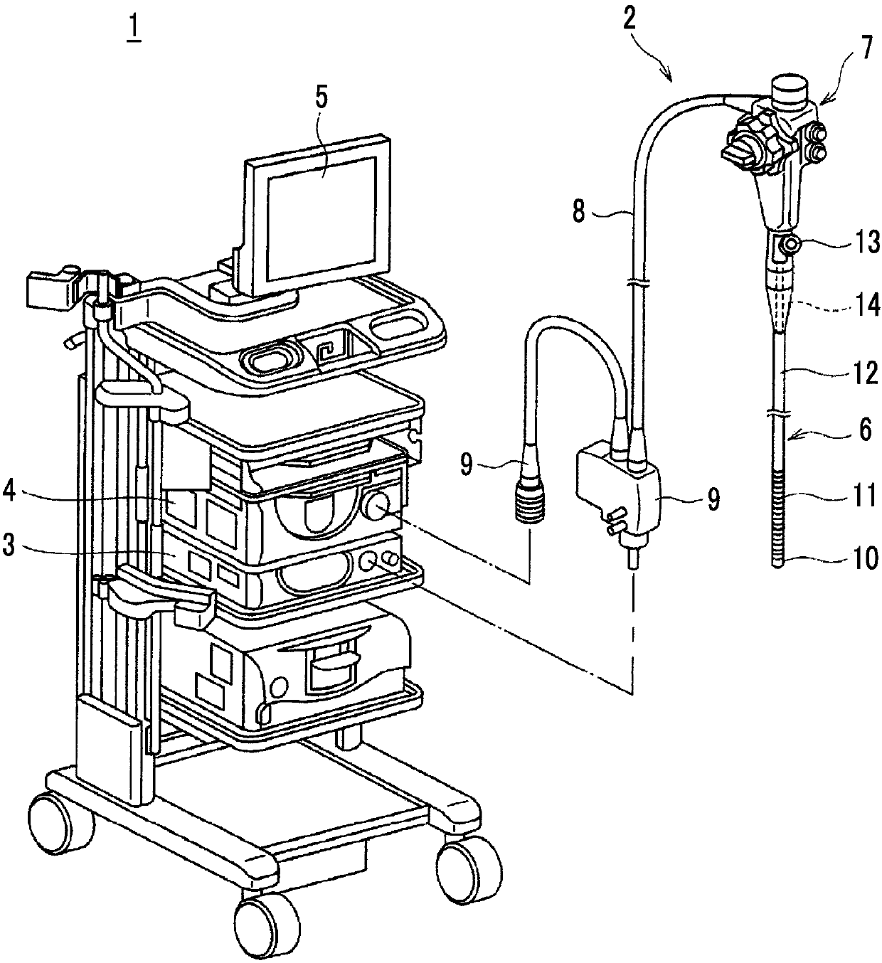
[0028] figure 1 An example of an endoscope system for describing an embodiment of the present invention is shown.

[0029] The endoscope system 1 includes an endoscope 2 , a light source unit 3 , and a processor unit 4 . The endoscope 2 has an insertion part 6 capable of being inserted into the subject, an operation part 7 connected to the insertion part 6, and a universal cord 8 extending from the operation part 7. The insertion part 6 is provided on the front end side of the endoscope 2, The universal cord 8 is provided on the base end side of the endoscope 2 . The insertion part 6 is composed of a front end part 10, a bending part 11 connected to the front end part 10, and a soft part 12 connecting the bending part 11 to the operation part 7. The front end part 10 is arranged at the front end of the insertion part 6 on the longitudinal axis. side, the soft portion...


PUM


Abstract

An endoscope includes an imaging device that is provided in a tip portion (10) of an insertion part (6) which can be inserted into a body cavity. The imaging device includes an image-sensor (21) thatan image receiving surface thereof is disposed crossing a longitudinal direction of the insertion part (6); a sensor connecting portion (30) which faces a surface of the image-sensor (21) on which connection terminals (26) are provided and is connected to the connection terminals (26); a wire connecting portion (31) which extends from an outer end of the sensor connecting portion (30) toward a base end side of the insertion part (6) and a center of the image receiving surface and has a circuit board (24) which is bent more than once; and a composite wire (27) of which a plurality of cables (28) connected to a cable connection surface (31a) of the wire connecting portion (31) facing the base end of the insertion part (6) are bundled. The composite wire (27) includes a first shield conductor(27B) provided around the plurality of cables (28) that are bundled and connected with the cable connection surface (31a).

Description

technical field [0001] The present invention relates to an endoscope. Background technique [0002] The imaging device mounted on the distal end of the insertion portion of the endoscope generally includes an image sensor and a circuit board on which the image sensor is mounted, and a cable inserted through the insertion portion is connected to the circuit board. [0003] In the imaging unit described in Patent Document 1, a solid-state imaging element and electronic components are mounted on a substrate, and lead portions of a plurality of signal lines inserted through cables are connected to predetermined regions of the substrate. Furthermore, in the imaging device described in Patent Document 2, a solid-state imaging element is mounted on one end of a flexible substrate, and a plurality of signal lines are connected to the other end of the bent flexible substrate. In addition, electronic components are mounted between one end and the other end of the flexible substrate. ...

Claims


Application Information

Patent Timeline
Patent Type & Authority Applications(China)
IPC IPC(8): A61B1/00A61B1/04
CPCA61B1/00071A61B1/04A61B1/00114A61B1/00124A61B1/128A61B1/051A61B1/00009A61B1/06A61B1/00096A61B1/00126A61B1/0057A61B1/01A61B1/045A61B1/05A61B1/0661
Inventor 北野亮
Owner FUJIFILM CORP
Why Eureka
Try Eureka