A clean egr loop system

A loop system and EGR valve technology, which is applied in the field of clean EGR loop system, can solve problems affecting EGR response speed and flow efficiency, power and economic loss, and high control strategy requirements, so as to improve response speed and flow efficiency, Extended service life and compact size

Inactive Publication Date: 2017-07-28
TONGJI UNIV
View PDF1 Cites 0 Cited by
  • Summary
  • Abstract
  • Description
  • Claims
  • Application Information

AI Technical Summary

Problems solved by technology

With the use of time, fine particles are easy to accumulate at the EGR valve, which is easy to cause blockage, affect the response speed and flow efficiency of EGR, and eventually cause the loss of power and economy, and aggravate the deterioration of particle emissions
[0005] Chinese patent CN 104879248 A discloses an anti-clogging EGR system and control method, including an EGR cooling unit, an exhaust heat exchange device, an NTP injection system, and a control module; the exhaust heat exchange device is installed at the end of the exhaust pipe end; there is a serpentine loop pipeline inside the exhaust heat exchange device, the inlet of the serpentine loop pipeline is connected to the NTP injection system, and the end of the injection pipeline at the outlet of the serpentine loop pipeline is provided with a nozzle, and the nozzle extends to the inlet of the EGR cooling unit The EGR cooling unit and the NTP injection system are all connected to the control module; the oxidation and removal of carbon deposits can be realized at a temperature lower than the ignition temperature of the engine exhaust particulate matter; the reaction can reach a suitable reaction by using the engine exhaust heat exchange device Temperature range: When one EGR cooler branch is working normally, the other EGR cooler branch is immediately regenerated to solve the blockage problem of the EGR system. However, the system has a complex structure, high control strategy requirements, and external NTP generation system, high cost, easy to fail, difficult to produce and apply

Method used


Image

  • A clean egr loop system
  • A clean egr loop system
  • A clean egr loop system

Examples


Embodiment 1

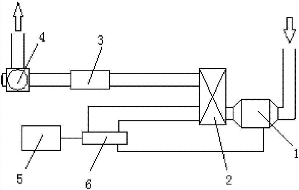
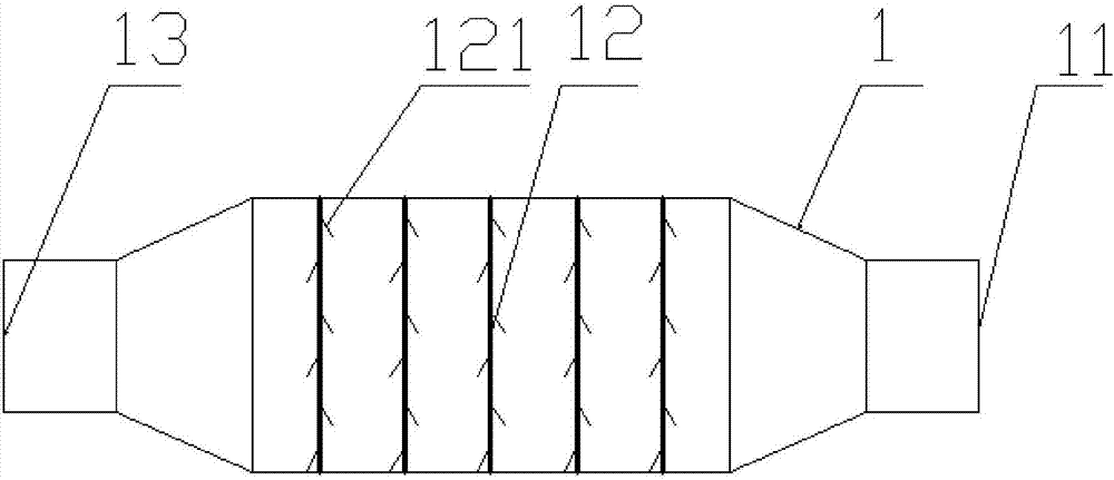
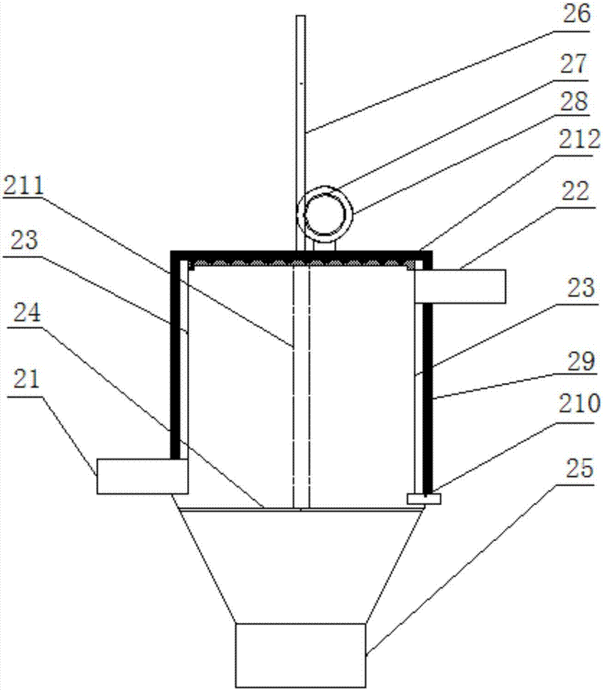
[0030] A clean EGR loop system such as Figure 1-4 As shown, it includes an EGR cooler 3 and an EGR valve 4, and also includes a charge condensation chamber 1 and a trap 2. The charge condensation chamber 1 is a cavity structure provided with an inlet 11 and an outlet 13. The charge condensation chamber 1 The cavity structure is provided with metal strips 12, and the metal strips 12 are arranged side by side at an interval of 20-30 mm inside the charged coagulation chamber 1. In this embodiment, the interval is 20 mm, and the metal strips 12 can be loaded with a pulsed DC voltage of 30-40 kv. For example, 35kv is used, the outlet of the charged coagulation chamber 1 is connected to the inlet of the trap 2, the outlet of the trap 2 is connected to the inlet of the EGR cooler 3, and the outlet of the EGR cooler 3 is provided with an EGR valve 4. The collector 2 is provided with an electrode plate 23, and there are two electrode plates of the collector 2, which are respectively a...


PUM


Abstract

The invention relates to a clean EGR loop system. The system comprises a charge coagulating chamber (1), a catcher (2), an EGR cooler (3) and an EGR valve (4); the charge coagulating chamber (1) is of a cavity structure, a metal strip (12) serving as a discharge electrode is arranged on the charge coagulating chamber (1), an electrode plate (23) is arranged in the catcher (2), an outlet of the charge coagulating chamber (1) is connected with an inlet of the catcher (2), an outlet of the catcher (2) is connected with an inlet of the EGR cooler, and the EGR valve is arranged on an outlet of the EGR cooler; compared with the prior art, the system has the beneficial effects that through the electric field effect, the content of NOx and HC in automobile engine waste gas can be reduced, the content of NOx and HC is reduced, corrosion to the EGR cooler and the EGR valve is reduced, and final emissions of the NOx are reduced; the system is low in cost, small in size, high in efficiency, small in resistance and easy to regenerate; the system can be additionally arranged in a GDI engine without complex modification, the service life of the EGR valve and the EGR cooler is greatly prolonged, and the response speed and the circulation efficiency of EGR are improved.

Description

technical field [0001] The invention relates to an EGR loop system, in particular to a clean EGR loop system used on a GDI engine. Background technique [0002] GDI engine (Gasoline Direct Injection Engine) is more and more widely used in passenger cars because of its good power performance, fuel economy and emission performance. The fuel of the GDI engine is directly injected into the cylinder, and the resulting uneven mixture of oil and gas and the wet wall of the fuel will significantly increase the quality and quantity of particulate matter emissions. A large number of experimental studies at home and abroad have shown that the amount of particulate matter emitted by GDI engines is significantly higher than that of traditional port injection engines. [0003] For a long time, the engine can reduce NOx by being equipped with a TWC (three-way catalytic converter). After the GDI engine is equipped with EGR (exhaust gas recirculation system), the power and economy have bee...

Claims


Application Information

Patent Timeline
Patent Type & Authority Patents(China)
IPC IPC(8): F02M26/35
Inventor 石秀勇陈琦倪计民刘越唐晨曦管志云
Owner TONGJI UNIV
Why Eureka
Try Eureka