Vent design method for casting die

A design method and casting mold technology, applied in the field of mold manufacturing, can solve problems such as difficult exhaust, achieve the effects of eliminating residual gas, ensuring integrity, and shortening the development cycle

Inactive Publication Date: 2011-04-13
JIANGLING MOTORS
View PDF5 Cites 1 Cited by
  • Summary
  • Abstract
  • Description
  • Claims
  • Application Information

AI Technical Summary

Problems solved by technology

[0003] The purpose of the present invention is to address the above-mentioned problems, to provide a method for venting design of casting molds, which can well solve the problem of difficult venting

Method used


Image

  • Vent design method for casting die
  • Vent design method for casting die
  • Vent design method for casting die

Examples


Embodiment 1

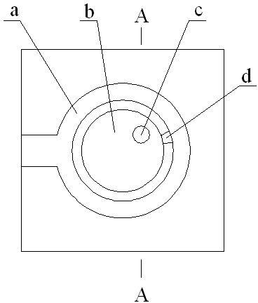
[0015] A venting design method for a casting mold comprises the following steps in sequence.

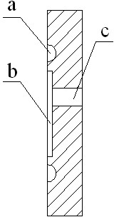
[0016] (1) Process a 2mm deep pit b at the part surrounded by the surrounding or semi-surrounding cavity a, and the edge of the pit b is 7mm away from the edge of the cavity a.

[0017] (2) Process the vent hole c at a position that does not interfere with other components of the mold within the range of the pit b.

[0018] (3) When testing the mold, a 0.1mm deep exhaust groove d is processed at the place where the gas stays in the mold cavity a, and the two ends of the exhaust groove d are respectively connected with the mold cavity a and the pit b.

Embodiment 2

[0020] A venting design method for a casting mold comprises the following steps in sequence.

[0021] (1) Process a 3mm deep pit b at the part surrounded by the surrounding or semi-surrounding cavity a, and the edge of the pit b is 9mm away from the edge of the cavity a.

[0022] (2) Process the vent hole c at a position that does not interfere with other components of the mold within the range of the pit b.

[0023] (3) When testing the mold, process a 0.13mm deep exhaust groove d at the place where the gas stays in the mold cavity a, and the two ends of the exhaust groove d are respectively connected with the mold cavity a and the pit b.

Embodiment 3

[0025] A venting design method for a casting mold comprises the following steps in sequence.

[0026] (1) Process a 5mm deep pit b at the part surrounded by the surrounding or semi-surrounding cavity a, and the edge of the pit b is 10mm away from the edge of the cavity a.

[0027] (2) Process the vent hole c at a position that does not interfere with other components of the mold within the range of the pit b.

[0028] (3) When testing the mold, a 0.15mm deep exhaust groove d is processed at the place where the gas stays in the cavity a, and the two ends of the exhaust groove d are respectively connected to the cavity a and the pit b.


PUM


Abstract

The invention relates to the field of die manufacturing, in particular to a vent design method for a casting die. The method comprises the following steps: (1) machining a pit b with the depth of 5mmin the position enclosed by an enclosure type or semi-enclosure type die cavity a, wherein the distance between the edge of the pit b and the edge of the die cavity a is 10mm; (2) machining a vent hole c in the position in which the vent hole can not interfere with other members of the die within the range of the pit b; and (3) in the die setting process, machining a vent trough d with the depth of 0.15mm in the position in which gas is retained in the die cavity, wherein both ends of the vent trough d are respectively communicated with the die cavity a and the pit b. By using the method of the invention, residual gas in the die cavity can be effectively eliminated, thereby ensuring that the integrity of the die product and shortening the development cycle of the die. The method is convenient and concise.

Description

technical field [0001] The invention relates to the field of mold manufacturing, in particular to an exhaust design method of a casting mold. Background technique [0002] With the rapid development of my country's foundry industry, casting molds have been widely used, and the design and manufacturing level of casting molds is also constantly improving. The traditional casting mold exhaust method uses vent holes and vent grooves to vent during core making. However, due to the complexity of fluid mechanics, it is difficult to accurately predict the flow of gas during venting during mold design. It is often necessary to add vent holes during the use of the mold, and the added vent holes are likely to interfere with other components such as heating pipes, and even cause poor exhaust and residual gas in the mold cavity, resulting in mold processing The products that come out have defects, especially the surrounding or semi-surrounding cavity. It is more difficult to add vent ho...

Claims


Application Information

Patent Timeline
Patent Type & Authority Applications(China)
IPC IPC(8): B22C7/06
Inventor 熊贵根王瑞平万修根熊秋宝温典行
Owner JIANGLING MOTORS
Why Eureka
Try Eureka