LED and dispensing method of LED fluorescent powder

A technology of fluorescent powder and fluorescent glue, which is applied in the direction of surface coating liquid devices, coatings, semiconductor devices, etc., which can solve problems affecting the consistency of LED light emission, low excitation efficiency of phosphor powder, uneven mixing of phosphor powder and silica gel, etc. The problem is to achieve the uniformity of light distribution and the consistency of color temperature, prevent the loss of luminous flux, and improve the effect of achieving the color zone

Active Publication Date: 2011-07-13
LEDMAN OPTOELECTRONIC HZ CO LTD
View PDF4 Cites 27 Cited by
  • Summary
  • Abstract
  • Description
  • Claims
  • Application Information

AI Technical Summary

Problems solved by technology

At present, there are mainly three kinds of coating processes for high-power LED phosphor powder: one is the method of filling fluorescent glue in the conventional bracket bowl. This process is prone to yellow circle phenomenon due to the thick fluorescent glue around it and is not easy to control. The excitation efficiency of the powder is low
The second is to uniformly coat the phosphor on the surface of the wafer through inkjet printing, photolithography, thin-film technology and other semiconductor processes. It is the way that some manufacturers try to dispense glue on the wafer, but the color zone achievement rate is low due to the easy flow of glue and the difficulty in controlling the amount of glue.
[0003] The Chinese invention patent with the application number of 200910190762.1 discloses a dispensing method of LED phosphor powder. The mixed solution formed by mixing phosphor powder and silica gel is dispensed on the LED bracket. However, the above dispensing process is in the process of dispensing. It is prone to wire drawing and affect the light color shift of LED lights, and the above invention is prone to bubbles during the mixing process of phosphor powder and silica gel, resulting in uneven mixing of phosphor powder and silica gel, resulting in precipitation that affects the consistency of LED light emission.

Method used


Image

  • LED and dispensing method of LED fluorescent powder
  • LED and dispensing method of LED fluorescent powder
  • LED and dispensing method of LED fluorescent powder

Examples


Embodiment Construction

[0026] In order to describe the technical content, structural features, achieved goals and effects of the present invention in detail, the following will be described in detail in conjunction with the embodiments and accompanying drawings.

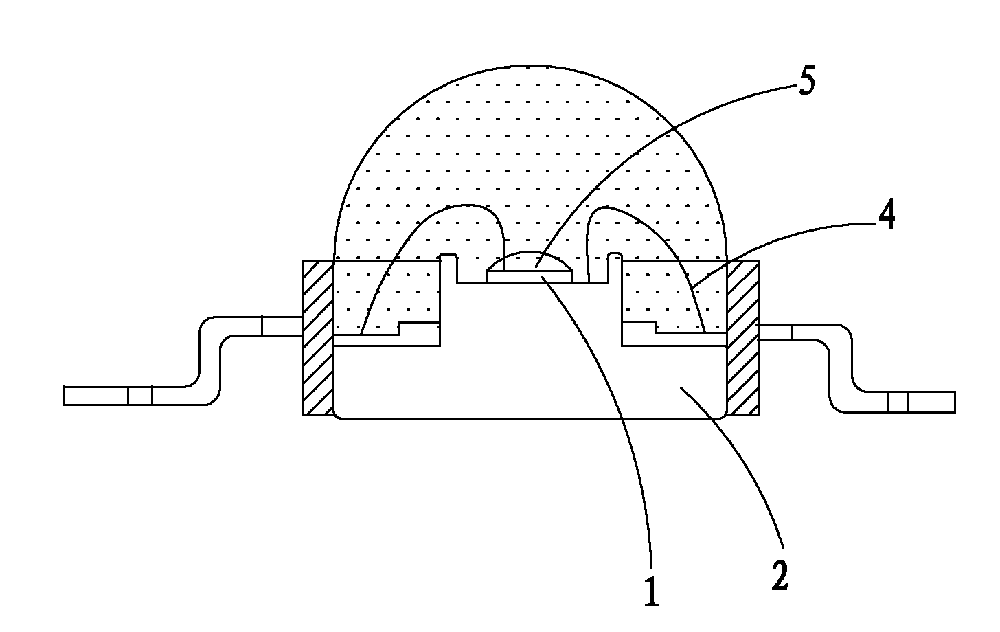
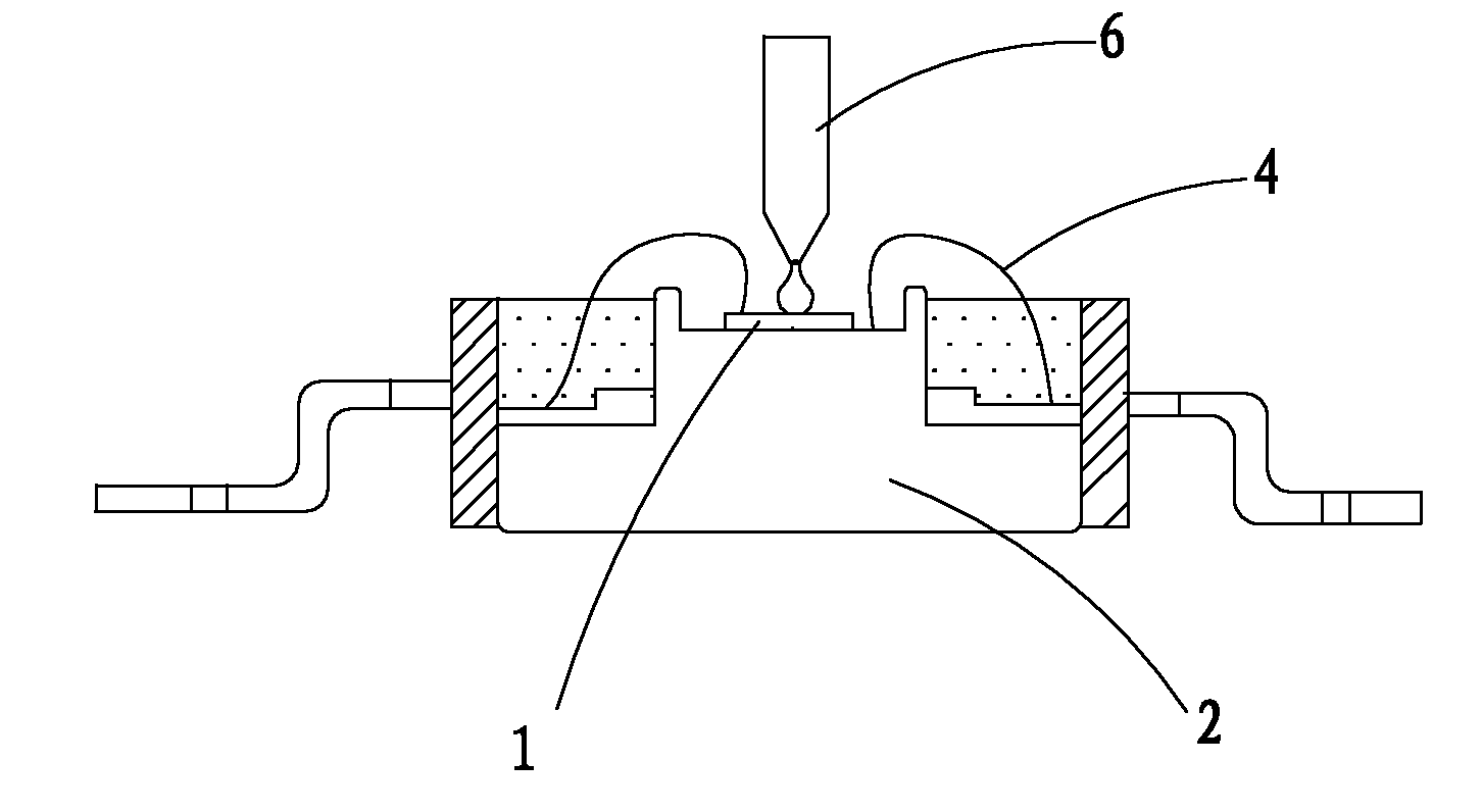
[0027] see figure 1 and figure 2 , the LED of the present invention includes a blue LED chip 1 and a concave socket 2 for carrying the blue LED chip 1 . The blue LED chip 1 is fixed in the concave receiving seat 2 by a primer.

[0028] In this embodiment, the primer is silver glue or insulating glue. The blue LED chip 1 has positive and negative electrodes, and the concave socket 2 has positive and negative electrodes. The positive and negative electrodes of the LED blue light chip 1 are welded to the positive and negative electrodes of the socket 2 respectively by wires 4 . The surface of the LED blue light chip 1 is coated with a layer of fluorescent glue 5. The fluorescent glue 5 is formed by mixing phosphor powder, nano powder and...


PUM


Abstract

The invention discloses an LED and a dispensing method of LED fluorescent powder. The dispensing method comprises the steps of: A, providing a bearing seat and an LED blue light chip, and fixing the LED blue light chip on the bearing seat through primer; B, respectively connecting the positive and the negative electrodes of the LED blue light chip with the positive and the negative electrodes of the bearing seat by using wires; C, mixing the fluorescent powder, nano powder and silicon gel according to a preset proportion to form fluorescent gel, and uniformly stirring; D, carrying out vacuumizing defoaming treatment on the fluorescent gel to eliminate remained gases in the fluorescent gel formed through mixing; E, coating the fluorescent gel on a dispensing position on the surface of the LED blue light chip at a dispensing height; and F, heating and curing the fluorescent gel coated on the surface of the LED blue light chip. The method has better effect on improving excitation efficiency of the fluorescent powder, uniformity of emitted light distribution and consistency of color temperature.

Description

technical field [0001] The invention relates to a dispensing method of LED and LED fluorescent powder. Background technique [0002] At present, the mainstream of high-power white light technology is blue light chip plus phosphor excitation to generate white light, and the coating process of phosphor powder is directly related to the relevant indicators of white light LED. Vertical wafers have become a development trend of high-power LEDs because of their uniform current distribution and ability to withstand high currents. At present, there are mainly three kinds of coating processes for high-power LED phosphor powder: one is the method of filling fluorescent glue in the conventional bracket bowl. This process is prone to yellow circle phenomenon due to the thick fluorescent glue around it and is not easy to control. Powder excitation efficiency is low. The second is to uniformly coat the phosphor on the surface of the wafer through inkjet printing, photolithography, thin-...

Claims


Application Information

Patent Timeline
Patent Type & Authority Applications(China)
IPC IPC(8): B05D5/06B05D7/24B05C11/10H01L33/00H01L33/50
CPCH01L2224/8592H01L2924/181H01L2924/19107H01L2224/48091H01L2224/48247H01L2924/00014H01L2924/00012
Inventor 李漫铁李志新扶韩伟何海生
Owner LEDMAN OPTOELECTRONIC HZ CO LTD
Why Eureka
Try Eureka