Degassing method of electric vacuum display device of plate glass

A technology for display devices and flat glass, which can be used in glass forming, glass reshaping, glass manufacturing equipment, etc., and can solve problems such as the inability to put air getters

Inactive Publication Date: 2006-08-02
CHANGCHUN INST OF OPTICS FINE MECHANICS & PHYSICS CHINESE ACAD OF SCI
View PDF0 Cites 1 Cited by
  • Summary
  • Abstract
  • Description
  • Claims
  • Application Information

AI Technical Summary

Problems solved by technology

However, the flat glass vacuum display device is an ultra-thin design, with a general

Method used


Image

  • Degassing method of electric vacuum display device of plate glass

Examples


Embodiment Construction

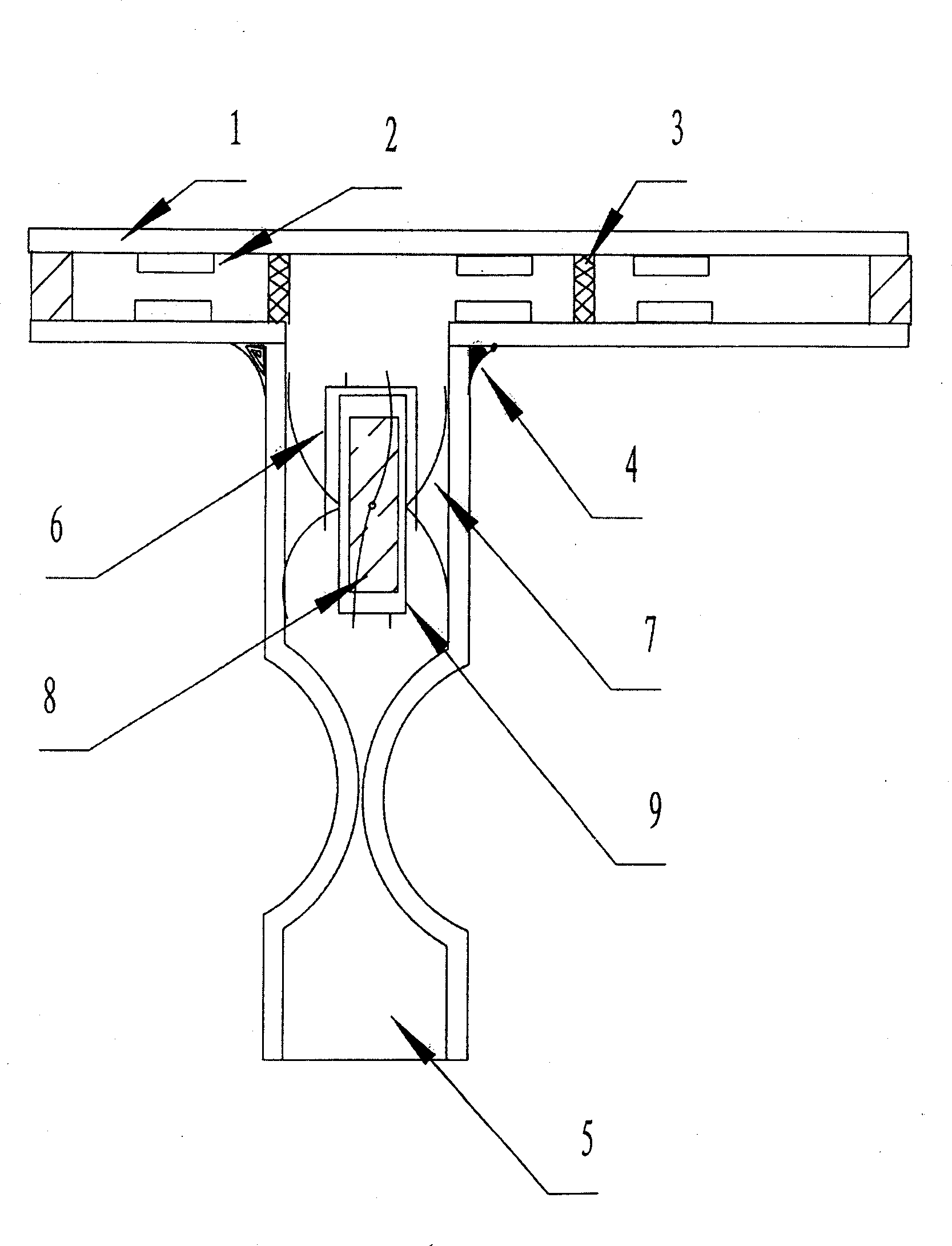
[0014] Press as figure 1 As shown, the air-absorbing device is assembled with the components of the air-absorbing glass tube 5, the anti-diffusion shell 6, the supporting tungsten wire 7, the evaporative air getter 8, and the short-circuit ring 9. The degassing device is sealed with a low-melting glass 4 and sintered and sealed at the sealing place of the glass 1 of the ultra-thin vacuum field emission display device. Assembled and sintered structures such as figure 1 , which is also a schematic diagram of an ultra-thin vacuum field emission display device with a getter.

[0015] After these components are sintered into a box, it can be connected to a vacuum system to draw a vacuum. After the degree of vacuum reaches the requirement, leave the proper length of the exhaust glass tube 5 and seal it with flame. Then put the processed ultra-thin tail tube of the vacuum field emission display device, that is, the exhaust glass tube 5, into the heating induction coil of the high-...


PUM


Abstract

The present invention belongs to the field of electronic device technology, and is especially degassing method for electric vacuum display device of plate glass. During the making process of very thin electric vacuum display device of plate glass, one specially designed degassing unit is set in the sealing part to eliminate residual gas after vacuum pumping. First, a bearing tungsten wire is inserted into the small hole of evaporated getter, a shorting ring on the getter and a diffusion preventing casing outside the shorting ring. Then the getter is set inside the glass tube in the pumping port. Finally, the glass tube is sealed with low smelting point glass to the sealing part. The present invention can eliminate residual gas without contaminating the work space and deforming the glass tube.

Description

technical field [0001] The invention belongs to the technical field of electronic devices, and relates to a flat glass electric vacuum display, in particular to a gas elimination method for a flat glass electric vacuum display device. Background technique [0002] At present, the getter is indispensable in the production of electric vacuum devices. Generally, the getter with a short-circuit ring is fixed at a suitable place inside the electric vacuum device, so that it is suspended in the electric vacuum device. After the gas glass tube is melted and sealed, a high-frequency heating furnace is used to heat and activate the getter in the short-circuit ring to achieve the purpose of absorbing residual gas and increasing the vacuum degree. However, the flat glass vacuum display device is an ultra-thin design, with a general thickness of about 200 μ, and it is impossible to put a getter in such a small space. The air getter must also be added, which means that a new technology ...

Claims


Application Information

Patent Timeline
IPC IPC(8): C03C27/00C03B23/20
Inventor 李志明宋航蒋红缪国庆赵海峰
Owner CHANGCHUN INST OF OPTICS FINE MECHANICS & PHYSICS CHINESE ACAD OF SCI
Why Eureka
Try Eureka