Solar panel window

A window surface and thin plate technology, applied in the field of solar energy harvesting, can solve the problem of window darkening

Inactive Publication Date: 2011-04-20
MORGAN SOLAR INC
View PDF0 Cites 16 Cited by
  • Summary
  • Abstract
  • Description
  • Claims
  • Application Information

AI Technical Summary

Problems solved by technology

The downside of this solution is that direct and reflected sunlight are e

Method used


Image

  • Solar panel window
  • Solar panel window
  • Solar panel window

Examples


Embodiment Construction

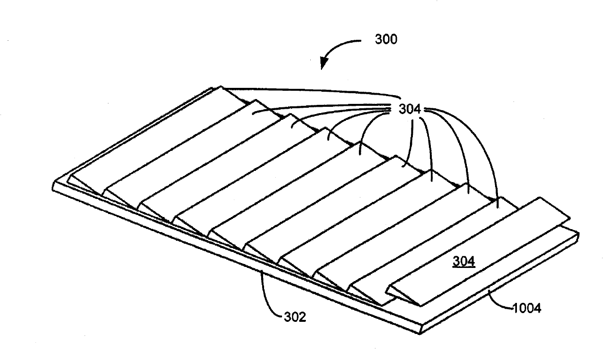
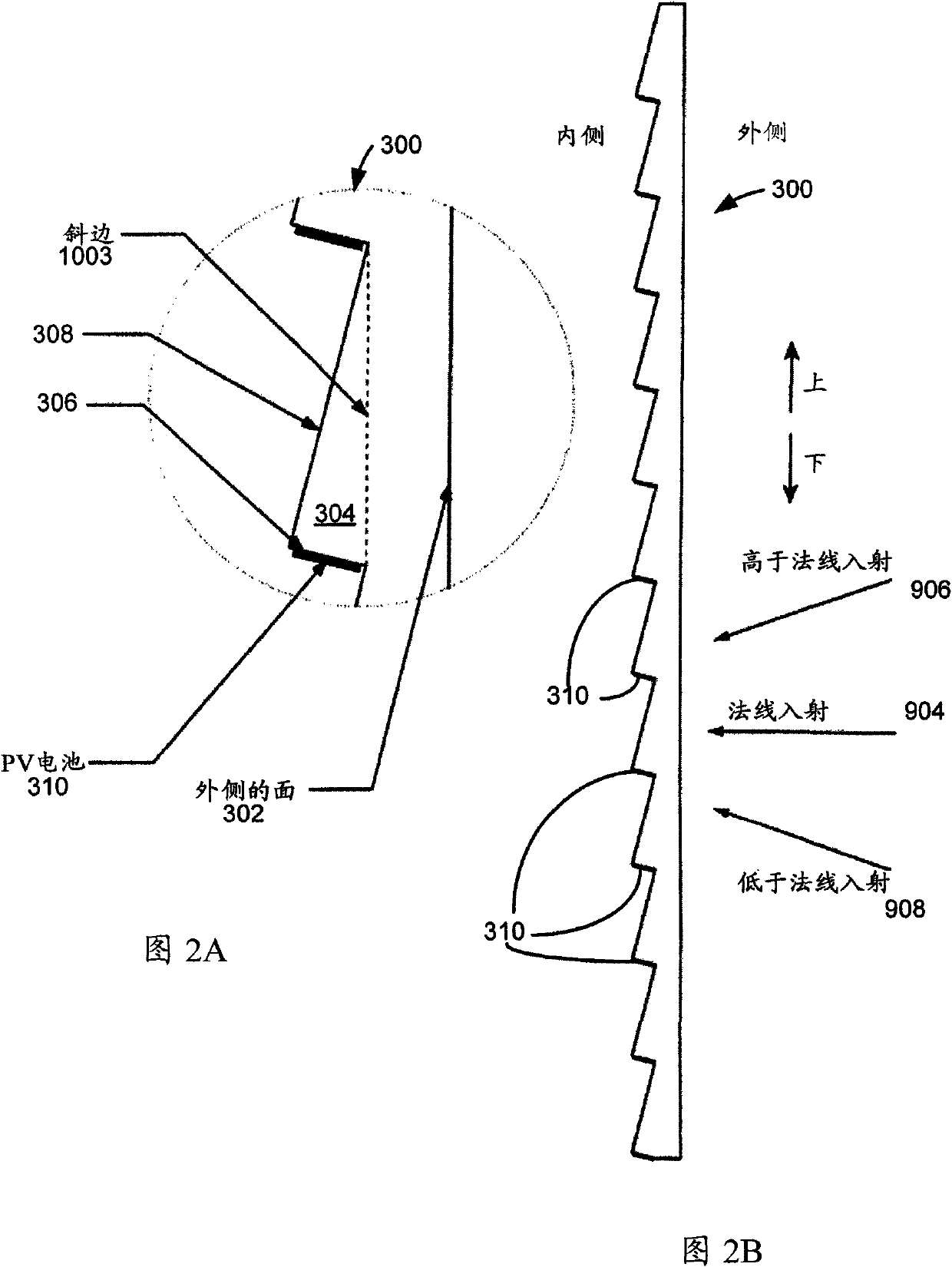
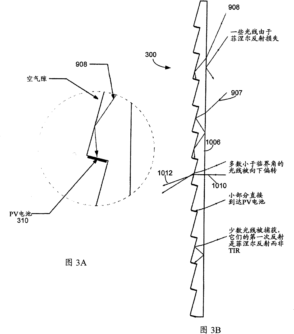
[0065] The solar panel window of the present invention differs from prior art solar window products in that it selects the light it absorbs and converts into electricity based on angle. Light incident on the solar panel window at a predetermined angle is transmitted through the window substantially unattenuated and substantially undeflected, or with little attenuation, while light incident from other angles is absorbed in the solar panel window acting as a waveguide. capture. The captured light is concentrated and propagated to a solar collector, such as a photovoltaic (PV) cell that converts the light into electricity.

[0066] Solar panel windows can be realized using a two-layer structure made of transparent optical materials. The first layer, called the capture layer, captures sunlight and directs it to the PV cells. The second layer, called the rectifying layer, redirects the light that was deflected but not captured by the trapping layer. The tuning layer reverses the...


PUM


Abstract

A solar panel window for mounting to a building. The window has an interior pane and an exterior pane adjacent to each other. The exterior pane has a first ridged surface and the interior pane has a second ridged surface, which is complementary to the first ridged surface. The exterior and interior panes are secured together with their ridged surfaces facing each other. A plurality of photovoltaic solar cells are mounted on the first ridged surface of the exterior pane. The solar panel window allows light impinging thereon through a pre-determined viewing angle to be transmitted inside the building. Light impinging on the window outside the pre-determined viewing angled is directed to the plurality of solar cells.

Description

technical field [0001] The present invention generally relates to harvesting of solar energy. More specifically, the present invention relates to solar light guide concentrators that can be used as windows. Background technique [0002] On many buildings, windows and walls receive a lot of sunlight, causing high temperatures and bright lights inside the building. This results in sub-optimal environmental conditions unless the building is air-conditioned and / or the shades are drawn. However, the presence of curtains prevents natural light from entering. [0003] Several companies offer solar panel windows with thin films of photovoltaic material to capture sunlight while allowing some transparency. The downside of this solution is that direct and reflected sunlight are equally attenuated, which means that the windows appear dark from any angle. That is, these windows attenuate direct sunlight and ambient light equally. These windows are not clear, but rather dark like su...

Claims


Application Information

Patent Timeline
IPC IPC(8): E06B7/00H01L31/052E06B3/67E04D13/18F24J2/16F24S23/77
CPCH01L31/0522E06B3/6715Y02E10/52E06B2009/2476Y02B10/10F24J2/50E06B2009/2417F24J2002/003F24S80/50F24S2070/62H01L31/0543H01L31/0547
Inventor 约翰·保罗·摩根
Owner MORGAN SOLAR INC
Why Eureka
Try Eureka