Fuel pump structure

A fuel pump and fuel technology, which is used in liquid fuel feeders, charging systems, engine components, etc., can solve the problems of expensive maintenance costs and difficult maintenance, and achieve the effect of reducing installation and compact installation.

Active Publication Date: 2011-04-27
HONDA MOTOR CO LTD
View PDF6 Cites 4 Cited by
  • Summary
  • Abstract
  • Description
  • Claims
  • Application Information

AI Technical Summary

Problems solved by technology

[0005] However, the above-mentioned parts of the conventional fuel pump are assembled in an integrated manner. When maintaining each part, since they can only be cleaned in the state that they have been assembled on the fuel pump, it is difficult t

Method used


Image

  • Fuel pump structure
  • Fuel pump structure
  • Fuel pump structure

Examples


Embodiment Construction

[0078] Below, according to Figure 1 to Figure 6 A first embodiment of the present invention will be described.

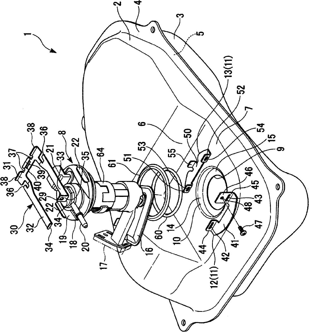
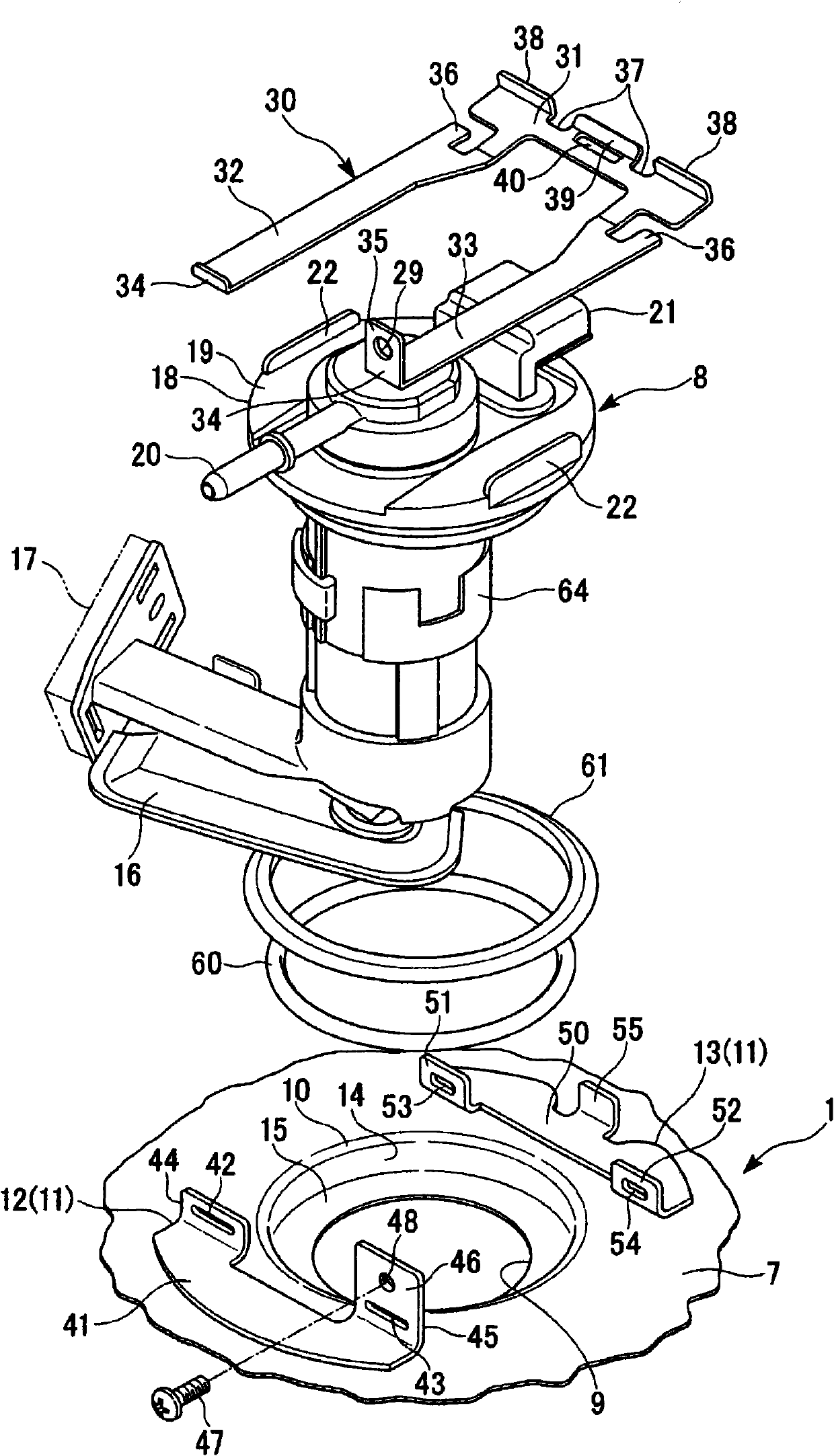
[0079] For example, if figure 1 In the shown fuel tank 1 of a motorcycle, an upper half 2 and a lower half 3 made of steel plates are welded to the fuel tank 1 by means of an upper flange 4 and a lower flange 5 . A recess 6 is formed in the upper half 2 , and a flat upper wall 7 is formed in the recess 6 .

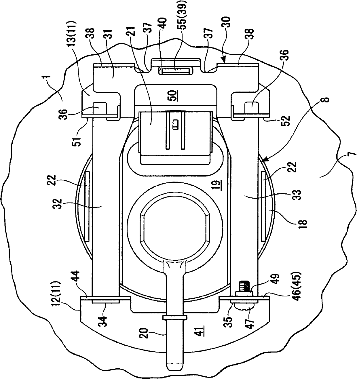
[0080] like Figure 1 to Figure 3 As shown, a circular insertion port 9 into which a fuel pump 8 is inserted is formed in the upper wall 7 . The insertion port 9 is formed at a position one step downward from the upper wall 7 via the stepped portion 10 . Around the insertion port 9, an engagement bracket 11 for locking a shutter 30 described later is welded and fixed. Specifically, the engaging bracket 11 is composed of an insertion seat 12 for receiving the bracket 30 and a fixing seat 13 for locking the baffle 30 , and the insertion seat 12 and the fixin...


PUM


Abstract

The invention aims to provide a fuel pump structure allowing assembling and disassembling disposable filters. The fuel pump structure of the invention comprises a main fuel pump body (8A) which is installed on a fuel box in a detachable manner and is provided at the end with a fuel intake port (67) extending along the axis (PJ) direction, a sensing device (17) with a detection part (69) at the arm part (68) extending from the main fuel pump body (8A) along the radial direction, a connecting part (74) disposed at the fuel intake port (67) of the main fuel pump body (8A), and a disposable filter (16) processing a filter part (75) extending from the connecting part (74) along the radial direction. The disposable filter (16) can be disposed at the fuel intake port (67) of the main fuel pump body (8A) in a detachable manner via the connecting part (74). Additionally, the extending direction of the filter part (75) of the disposable filter (16) is set to be identical to that of the sensing device (17).

Description

technical field [0001] The invention relates to a structure of a fuel pump. Background technique [0002] A fuel tank of a vehicle such as a motorcycle is equipped with a built-in fuel pump. Such a fuel pump is constituted by a pump main body, a sensor device (sender), and a primary filter, and has a structure in which these pump main body, sensor device, and primary filter are assembled integrally (see Patent Document 1). [0003] Patent Document 1: Japanese Unexamined Patent Publication No. 2004-232572. [0004] Conventionally, when maintaining the primary filter, it was necessary to remove the fuel pump from the fuel tank for maintenance. [0005] However, the above-mentioned parts of the conventional fuel pump are assembled in an integrated manner. When maintaining each part, since they can only be cleaned in the state that they have been assembled on the fuel pump, it is difficult to adequately clean the parts. the problem of maintaining it. [0006] If the primary ...

Claims


Application Information

Patent Timeline
IPC IPC(8): F02M37/04F02M37/22
Inventor 上野正树铃木祥介平松明人
Owner HONDA MOTOR CO LTD
Why Eureka
Try Eureka