Design method of initial off-position angle of hot-rolling H-shaped steel flying shear

A design method and technology for flying shears, which are applied in the field of metallurgical hot rolling technology, can solve the problems that the opening of upper and lower shearing edges cannot meet the technological requirements, the development of flying shears is unfavorable, and it is difficult to determine the spatial orientation of connecting rods and rockers. Achieve the effect of high calculation accuracy, good versatility and good understanding

Inactive Publication Date: 2011-04-27
WISDRI ENG & RES INC LTD
View PDF4 Cites 12 Cited by
  • Summary
  • Abstract
  • Description
  • Claims
  • Application Information

AI Technical Summary

Problems solved by technology

If the initial stop angle of the flying shear is too large, the opening of the upper and lower cutting edges may not meet the process requirements; if the initial stop angle of the flying shear is too small, the flying shear may not be able to complete braking within 360° Added the complex control process of the flying shear back swing
[0004] In the existing engineering design and related literature, generally only the running track of the shear blade of the crank linkage mechanism, the speed and acceleration in the x and y directions are calculated, and some kinematic parameters of the shear blade are obtained. In th

Method used


Image

  • Design method of initial off-position angle of hot-rolling H-shaped steel flying shear
  • Design method of initial off-position angle of hot-rolling H-shaped steel flying shear
  • Design method of initial off-position angle of hot-rolling H-shaped steel flying shear

Examples


Embodiment Construction

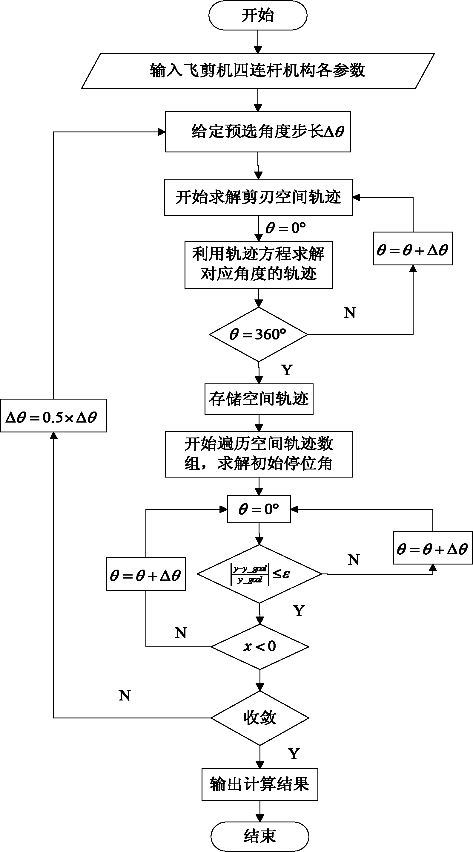
[0031] (1) The logical expression of the parameters required for the space trajectory of the cutting edge of the flying shear

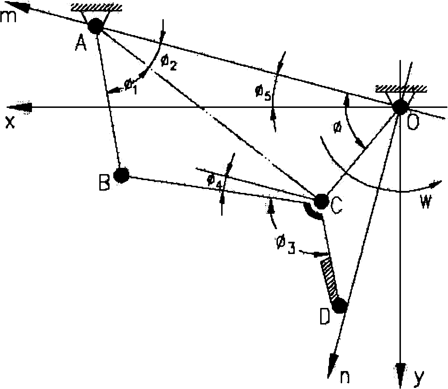
[0032] The original drawing of the upper cutting edge of the flying shear (the lower cutting edge is symmetrical to the rolling center line), as shown in figure 1 shown.

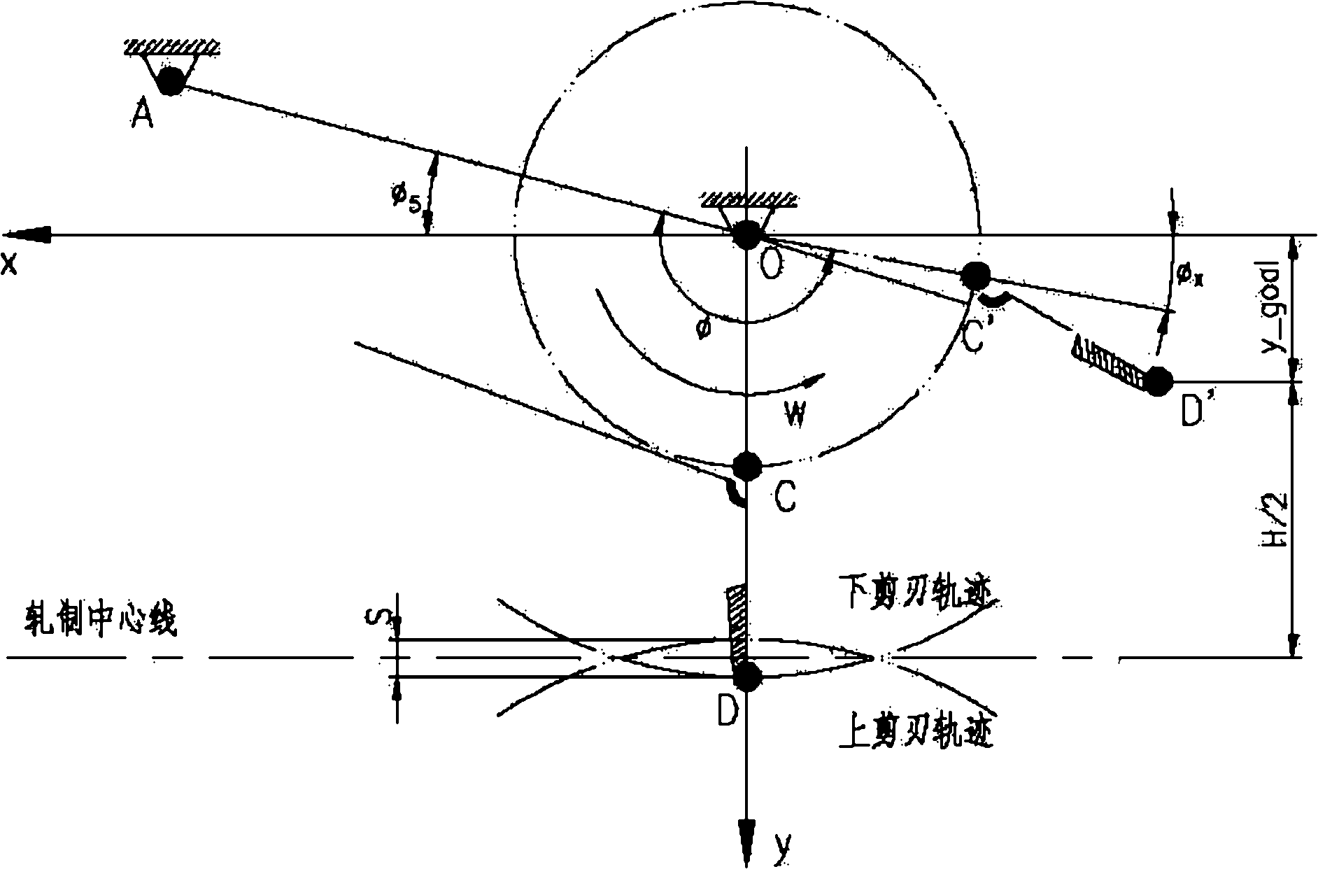
[0033] It is composed of connecting rod OC, rod AB and rod BCD: the rod BCD is welded by rod BC and rod CD, and the upper cutting edge is connected with the connecting rod CD through the blade seat. The crank OC is driven by a motor to make periodic revolving motions around its center of rotation O. It drives the connecting rod BCD and the upper cutting edge to move along the predetermined track through the hinge pair. One end B of the connecting rod BCD is connected with the rocker AB through a joint, and the rocker AB moves around the point A within a certain range. Before starting to cut, the upper cutting edge of the flying shear will stay at a specified position and form a c...


PUM


Abstract

The invention relates to the technical field of metallurgy hot rolling, in particular to a design method of the initial off-position angle of a hot-rolling H-shaped steel flying shear. The invention designs the initial off-position angle of the flying shear with a cyclic iterative numerical method and aims to provide a design method of the initial the off-position angle of a hot-rolling H-shaped steel flying shear, which has good popularity, high adaptability, high calculation accuracy and the like and is used for more clearly finishing design of the flying shear. The invention can serve as abeneficial design supplement for the crank connecting link design of the flying shear, can truly reflect the principle of the design of the flying shear mechanism, provides a powerful theory support for accurately controlling the flying shear, is convenient to submit the perfect function specification of the flying shear equipment, can be used for solving the trajectory, the speed of each direction and the angular velocity of each node of the flying shear.

Description

technical field [0001] The invention relates to the technical field of metallurgical hot-rolling technology, in particular to a method for designing the initial stop angle of a hot-rolled H-shaped steel flying shear. Background technique [0002] Flying shear is one of the important equipments in the steel rolling production line. It is arranged in front of the finishing rolling unit. It is used for cutting and breaking the head and tail of the rolled steel during hot rolling of section steel. The quality of its work performance directly affects the production efficiency of the rolling line and the quality of the product cut. With the development of continuous rolling mills, flying shears have been used more and more widely. [0003] According to the requirements of the hot-rolled H-beam production process, the flying shear adopts the start-stop type, and the type is a crank connecting rod. It uses the eccentricity of the crankshaft to form a rocker to complete the predeter...

Claims


Application Information

Patent Timeline
IPC IPC(8): G06F17/50
Inventor 严国平许燚罗新华刘斌奇盛汉桥
Owner WISDRI ENG & RES INC LTD
Why Eureka
Try Eureka