
Scanning type display device control circuit

A display device and control circuit technology, applied in the field of circuits, can solve problems such as longer time and lower refresh frequency, and achieve the effects of reducing bandwidth, increasing refresh frequency, and avoiding repeated transmission

Active Publication Date: 2011-05-04
MACROBLOCK INC
View PDF1 Cites 14 Cited by
  • Summary
  • Abstract
  • Description
  • Claims
  • Application Information

AI Technical Summary

Problems solved by technology

In addition, because the time required to display a complete screen becomes longer, the refresh rate (refresh rate) will also decrease.

Method used


Image

  • Scanning type display device control circuit
  • Scanning type display device control circuit
  • Scanning type display device control circuit

Examples


Embodiment Construction

[0045] The detailed features and advantages of the present invention are described in detail below in the embodiments, the content of which is sufficient to enable any person familiar with the relevant art to understand the technical content of the present invention and implement it accordingly, and according to the content disclosed in this specification, the patent scope of the application and the accompanying drawings , anyone skilled in the relevant art can easily understand the related objects and advantages of the present invention. The following examples further illustrate the concept of the present invention in detail, but do not limit the scope of the present invention in any way.

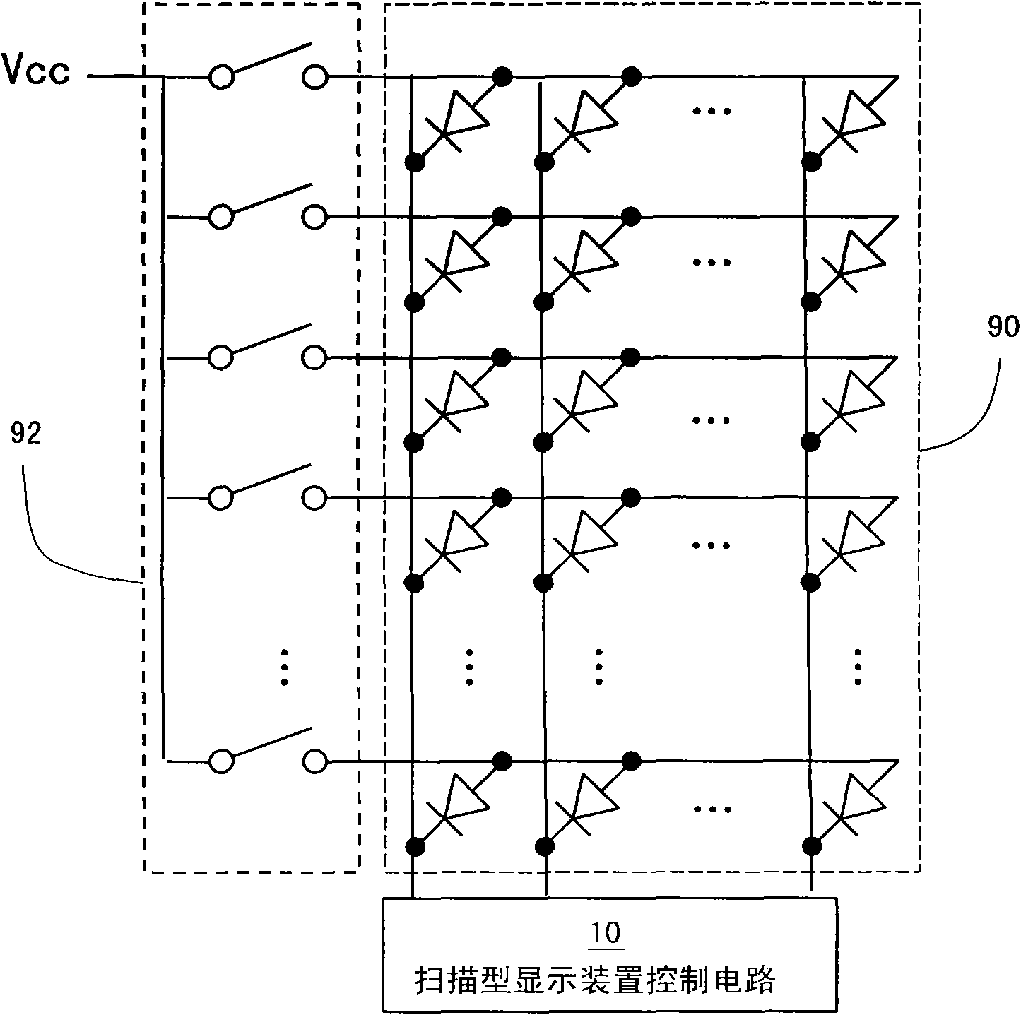
[0046] Please refer to figure 1 , is a structural diagram of the LED display device 90 . The LED display device 90 is a one-line scanning display screen. The LED display device 90 needs to use a switcher 92 together. For example, the LEDs on the LED display device 90 can be divided into...


PUM


Abstract

The invention provides a scanning type display device control circuit which is suitable for receiving successive frame data and driving a light-emitting diode display device according to the successive frame data. The scanning type display device control circuit comprises a ping-pong storage area, a data storage controller, a row scanning controller, a buffer module and a scattered type pulse width modulation signal generating device. The scanning type display device control circuit can repeatedly and circularly utilize the frame data so as to avoid repeated transmission of mass data. Therefore, the bandwidth required for inputting the data can be greatly reduced. In addition, the scattered type pulse width modulation signal generating device can scatter a pulse width modulation signal with longer cycle into a plurality of scattered type pulse width modulation signal with a shorter cycle, thus refreshing frequency can be effectively improved under the condition of not altering the bandwidth of the input data.

Description

technical field [0001] The present invention relates to a circuit, in particular to a control circuit for a scanning display device. Background technique [0002] In recent years, the manufacturing cost of light-emitting diodes (Light-Emitting Diode, LED) has dropped significantly. Therefore, LED displays have been widely used in various occasions, such as gymnasiums, outdoor billboards, and the like. [0003] Light-emitting diode display devices usually use thousands of light-emitting diodes as display pixels. Pixels showing different brightness respectively can form a picture, and multiple pictures can be presented sequentially in time to form a dynamic image. [0004] These pixels are respectively controlled via the controller. According to the input data, the controller sends on or off signals to the LED driver to control the brightness of the pixels. [0005] Generally speaking, the dynamic image switches about 60 frames per second, that is to say, the switching fre...

Claims


Application Information

Patent Timeline
IPC IPC(8): G09G3/32G09G3/20
Inventor 吴肯唐史富洋
Owner MACROBLOCK INC
Features
  • Generate Ideas
  • Intellectual Property
  • Life Sciences
  • Materials
  • Tech Scout
  • Unparalleled Data Quality
  • Higher Quality Content
  • 60% Fewer Hallucinations
Learn More