Method and device for monitoring the quality, particularly the stiffness and the phase, of a hydroelastic joint

An elastic joint, hydro-elastic technology, applied in the direction of measuring device, testing of mechanical components, testing of machine/structural components, etc., can solve the problem of not allowing to test the characteristics of hydraulic components

Inactive Publication Date: 2011-05-04
ANVIS SD FRANCE
View PDF3 Cites 5 Cited by
  • Summary
  • Abstract
  • Description
  • Claims
  • Application Information

AI Technical Summary

Problems solved by technology

The method disclosed in this patent application does not allow to examine the characteristics of the hydraulic components of the hydroelastic joint

Method used


Image

  • Method and device for monitoring the quality, particularly the stiffness and the phase, of a hydroelastic joint
  • Method and device for monitoring the quality, particularly the stiffness and the phase, of a hydroelastic joint
  • Method and device for monitoring the quality, particularly the stiffness and the phase, of a hydroelastic joint

Examples


Embodiment Construction

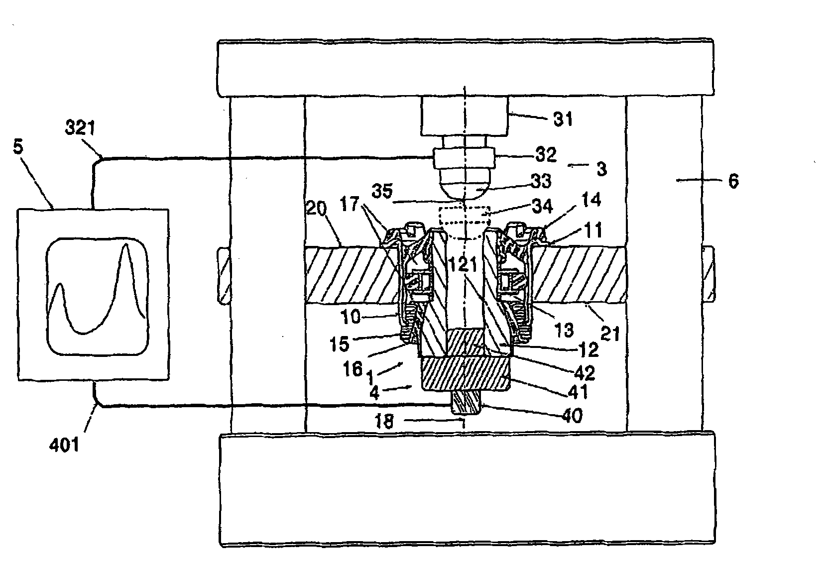
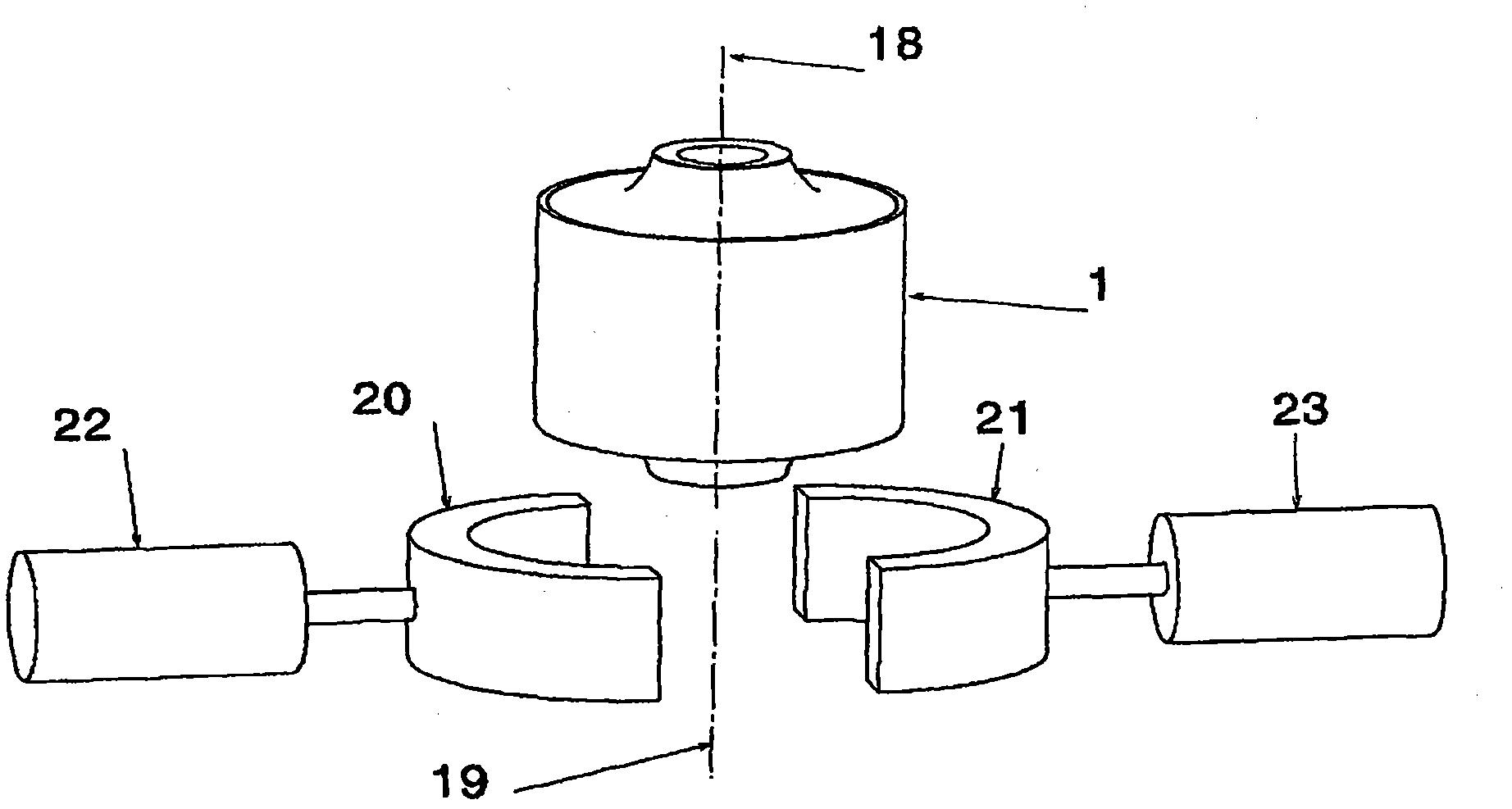
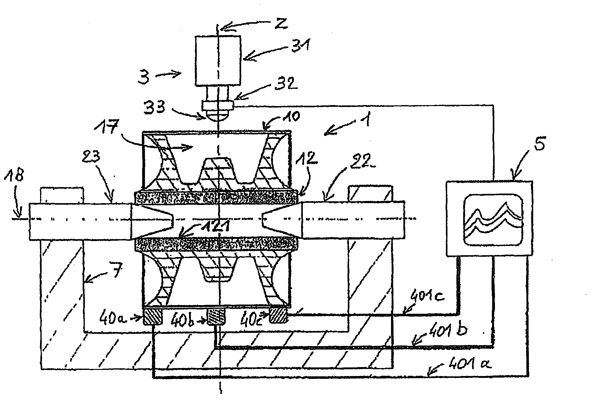
[0044] exist figure 1In it, a hydroelastic joint 1 comprises an outer cylindrical metal support element 10 with a collar 11 folded down, an inner support element 12 initially coaxial with the outer support element 10, a plastic spacer fitted on the inner support element 12 13. Several elastic sections 14, 15 and 16 machined to increase the viscosity and glued or fitted on one or the other support element, and two hydroelastic cavities 17. In the present exemplary embodiment, the elastic joint 1 has a theoretical working axis 18 which is likewise the axis of symmetry of the elastic joint. During the production cycle, this elastic joint is placed between two housings 20 and 21 which press the elastic joint on the outer support element 10 with a force sufficient to avoid any slipping of the elastic joint during impacts, while Permanent deformation thereof is also avoided. In this embodiment, the circular collar 11 of the outer support element 10 rests on the two half-shells 20 ...


PUM


Abstract

Method for monitoring the quality, particularly the stiffness and the phase, of a joint intended to connect two other parts while filtering the transmission of vibrations between these other two parts, said joint being called on to work axially, radially or in torsion, optionally having one or more hydroelastic chambers and being composed of two concentric cylindrical reinforcements, the inner reinforcement being largely situated within the volume defined by the outer reinforcement, these two reinforcements being connected by a set of rubber or elastomer components and, where appropriate, plastic components and metal parts, said reinforcements themselves being respectively fastened to the other two parts that are connected by the joint, by applying an impact monitoring technique at the rate of the production line on which the joints are produced, that is to say less than 10 seconds of cycle time, in order to identify the good from the poor parts during a frequency analysis of the oscillation of the impacted joint region, characterized in that phase shift values of the frequency analysis are compared with an authorised phase shift bandwidth.

Description

technical field [0001] The present invention relates to a method and a device for controlling the properties of a hydro-elastic joint, in particular stiffness and phase. The most common fields of application of these devices are those involved in establishing the ground contact of automobiles or utility vehicles, especially when they are used as spacers between the saddle and the chassis or as motor supports or as transmission elements or for establishing the vehicle's This is the case for torsional vibration absorbers of ground-contacting elements. Background technique [0002] In the following, the generic term "elastic joint" will be used to denote these spacers, supports or articulations, except in cases where specific characteristics of one or the other product are stated. [0003] These elastic joints are located on the contact surfaces of the two parts to be connected and are used to filter and change the phase of the vibrations transmitted between the two parts to b...

Claims


Application Information

Patent Timeline
Patent Type & Authority Applications(China)
IPC IPC(8): G01M7/08G01M13/00
CPCG01M7/08G01M13/022
Inventor 塞尔日·韦尔热
Owner ANVIS SD FRANCE
Why Eureka
Try Eureka