Pressure flange

A pressure method, annular groove technology, applied in flange connection, pipe/pipe joint/pipe fitting, passing element, etc., can solve the problems of medium leakage, decreased pipe hardness, easy pipe breakage, etc. Increased connection firmness and good sealing performance

Inactive Publication Date: 2011-05-11
吕增和
View PDF1 Cites 2 Cited by
  • Summary
  • Abstract
  • Description
  • Claims
  • Application Information

AI Technical Summary

Problems solved by technology

Since the pressure flange has an annular groove on the outer circumference of the pipe, the hardness of the pipe decreases. Under high pressure, the pipe is easy to break and the medium leaks.

Method used


Image

  • Pressure flange
  • Pressure flange
  • Pressure flange

Examples


Embodiment Construction

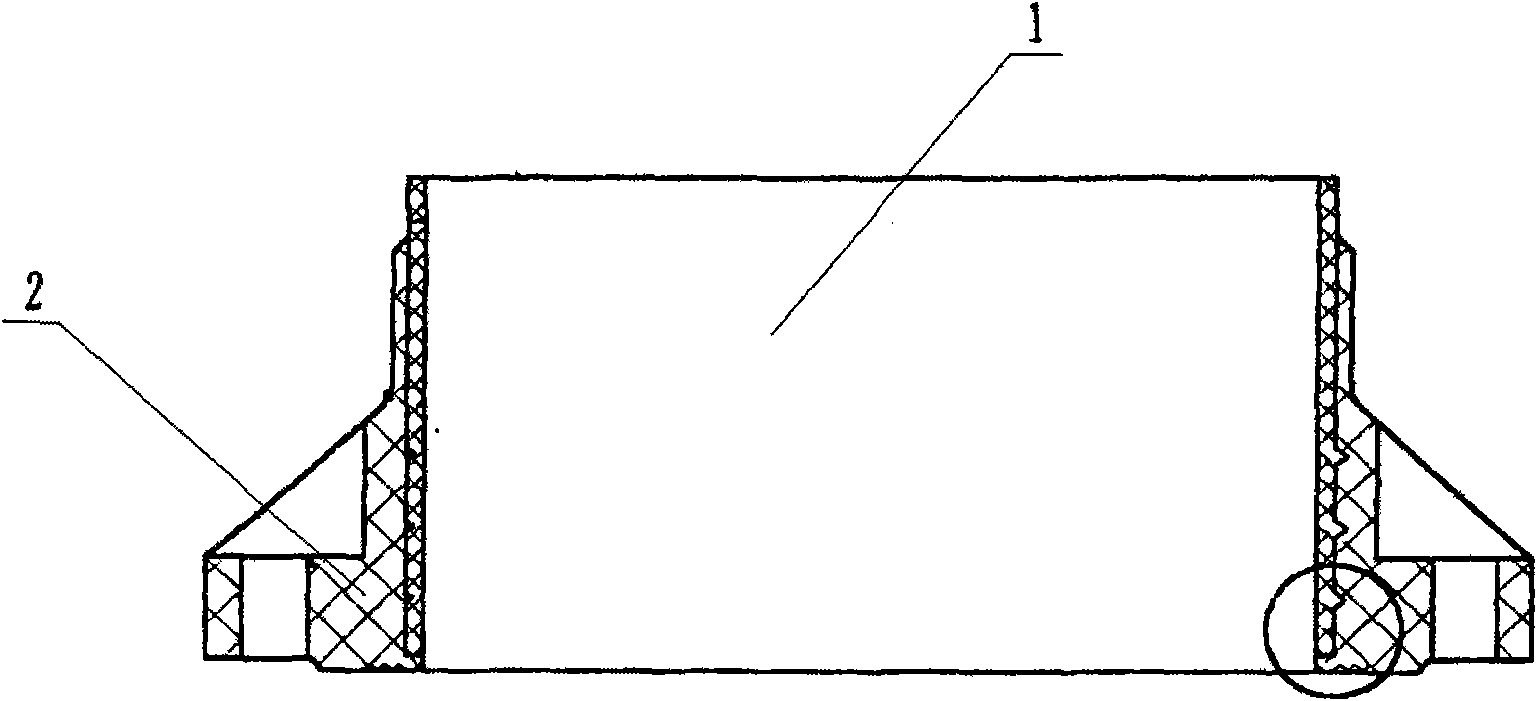
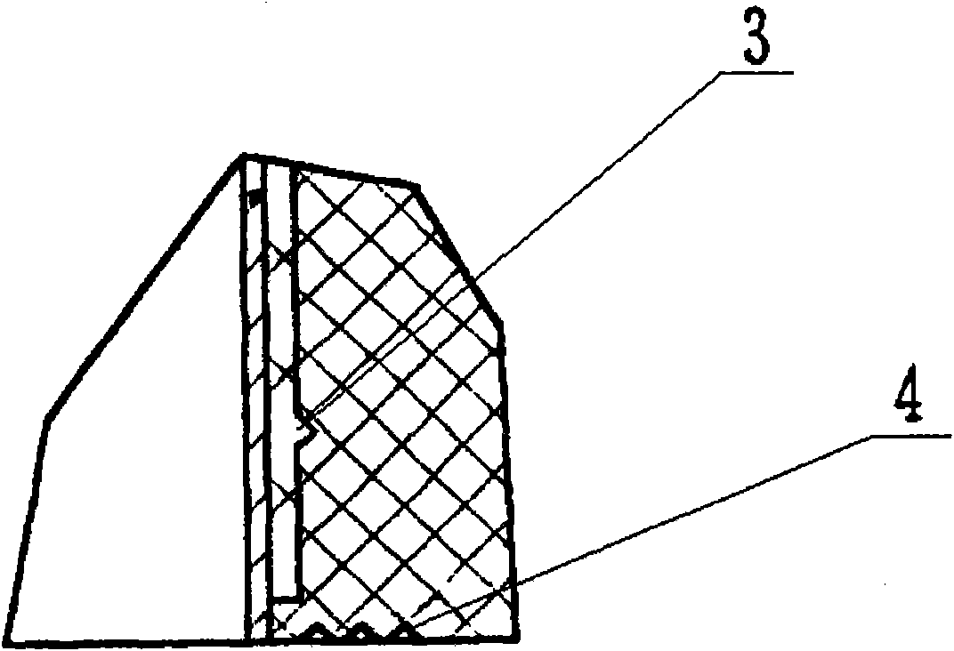
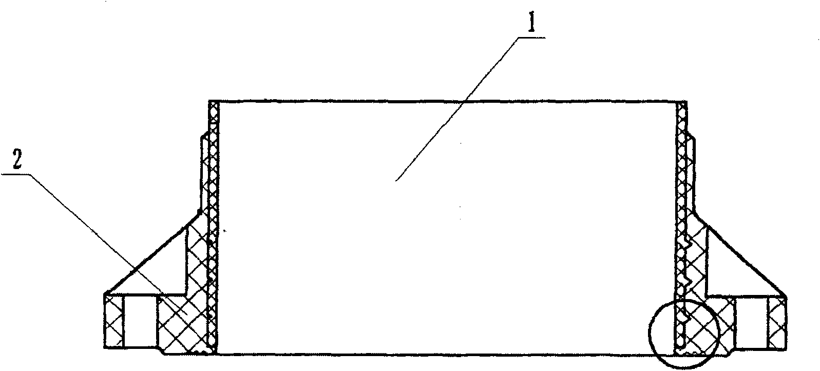
[0017] Below in conjunction with accompanying drawing and embodiment, the present invention is described in further detail, but does not constitute any restriction to the present invention:

[0018] according to figure 1 , 2 It can be seen that the pressure flange of the present invention includes a pipeline 1 and a flange 2 connected to the outer periphery of the pipeline 1. The inner circumference of the flange 2 is provided with an annular groove 3; the working surface of the flange 2 is There are at least two annular grooves 4 centered on the pipe 1 on the surface; the annular grooves 4 are concentrically distributed with the pipe 1 as the center; the planes formed by the annular grooves 3 are parallel to each other and distributed at equal intervals ; The longitudinal section shape of the annular grooves 3 and 4 is an isosceles triangle. The outer circumference of the pipe and the flange, and the working surface of the flange are fixedly connected by bonding.


PUM


Abstract

The invention discloses a pressure flange which comprises a pipeline and a flange plate matched with and connected to the outer periphery of the pipeline. The flange is characterized in that the inner periphery of the flange plate is provided with an annular groove. The pressure flange has the advantages of safety, long service life and good sealing performance and is suitable for being used under high working pressure.

Description

Technical field: [0001] The invention relates to the field of pipeline connectors, in particular to a pressure flange suitable for utilization of waste heat from firewood stoves. Background technique: [0002] At present, most of the FRP flanges on the market adopt a flat pressing surface structure. The bonding firmness between the flange of this structure and the flanged pipe is low, and the pre-compression effect is poor, resulting in the transportation in the pipeline. When the material pressure is high, the sealing gasket is easy to be squeezed out to compress the sheet, and the sealing effect is poor, so it is only suitable for use in low pressure occasions. Chinese patent, patent number: 02254397.X, discloses a pressure flange, which includes a short pipe and a flange fitted on the outer periphery of the short pipe; the lower part of the outer periphery of the short pipe is provided with an annular groove. Since the pressure flange is provided with an annular groove o...

Claims


Application Information

Patent Timeline
Patent Type & Authority Applications(China)
IPC IPC(8): F16L23/032
Inventor 吕增和
Owner 吕增和
Why Eureka
Try Eureka