Power amplifier linearization correcting circuit and method based on multi-channel feedback

A multi-channel feedback and correction circuit technology, applied in the field of linearization and linearization of power amplifiers, can solve problems such as difficult to satisfy wide frequency band at the same time, difficult to collect feedback signals, etc.

Active Publication Date: 2011-05-11
CHENGDU KAITENG SIFANG DIGITAL RADIO & TELEVISION EQUIP CO LTD
View PDF6 Cites 35 Cited by
  • Summary
  • Abstract
  • Description
  • Claims
  • Application Information

AI Technical Summary

Problems solved by technology

[0016] In view of the fact that the existing baseband predistortion power amplifier linearization technology does not focus on solving the linearity requirements and high-speed acquisition problems of the feedback channel in the case of large bandwidth signal transmission, the present invention aims to provide a large bandwidth transmitter baseband predistortion power amplifier linearization based on multi-channel feedback. A correction circuit and method for large-bandwidth transmitter power amplifiers to solve the problems that both broadband and high linearity of the feedback channel are difficult to satisfy at the same time in the adaptive baseband pre-distortion system of a large-bandwidth transmitter power amplifier, and that it is difficult to collect broadband feedback signals, so as to realize the power amplifier of a large-bandwidth signal transmitter Baseband pre-distortion linearization correction, so as to adapt to the development trend of communication broadband and mobility, and improve the efficiency of the transmitter

Method used


Image

  • Power amplifier linearization correcting circuit and method based on multi-channel feedback
  • Power amplifier linearization correcting circuit and method based on multi-channel feedback
  • Power amplifier linearization correcting circuit and method based on multi-channel feedback

Examples


Embodiment Construction

[0056] The present invention will be further described below according to the accompanying drawings.

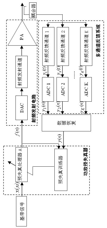
[0057] Such as figure 2 As shown, the output signal of the power amplifier passes through the coupler and enters the K channel feedback system, where K is not less than 2. The K-channel feedback system completes the data collection of each channel, the down-conversion of the signal, and finally uses the analog-to-digital conversion circuit ADC to convert the signal into a digital signal y 1 (n), y 2 (n),...y K (n). The data restorer receives the output data y of each channel from the feedback system 1 (n), y 2 (n),...y K (n), recovering the baseband data block y(n) having the same frequency domain structure as the output signal of the power amplifier. In the power amplifier predistorter, the parameters of the predistortion processor A are updated by using y(n), x(n) and the output signal f(n) of the predistortion processor A. In the process of calculating the paramet...


PUM


Abstract

The invention discloses a power amplifier linearization correcting circuit and method based on multi-channel feedback, relates to a linearization technology in the technical field of communication, and aims to provide a power amplifier linearization correcting circuit and method capable of self-adaptively regulating a predistortion parameter of a system by tracking the linearization characteristic of a radio frequency power amplifier. The power amplifier linearization correcting method is technically characterized in that a signal output by a power amplifier is subjected to frequency spectrumdivision and is coupled to a feedback system by utilizing a plurality of paths of channels; a data recovery circuit recovers a plurality of paths of feedback information to form a path of signal; a predistortion trainer calculates the predistortion parameter by utilizing a baseband signal and a recovered feedback signal; a predistortion trainer A adds a predistortion signal complementing a nonlinear distorted signal of the power amplifier according to the predistortion parameter; and the predistortion signal in the baseband signal is counteracted in the power amplifier, thereby realizing the linearization correction of the power amplifier. The invention is mainly used for nonlinear predistortion correction of a radio frequency signal emission system.

Description

technical field [0001] The invention relates to a linearization technology in the field of communication technology, in particular to a power amplifier linearization technology used in a radio frequency wireless communication transmitter. Background technique [0002] A power amplifier (hereinafter referred to as a power amplifier) ​​is an indispensable component in a communication system, and there is inevitably nonlinearity between its input and output. Early wireless communication was based on the constant envelope modulation technology which is insensitive to the nonlinearity of power amplification, which can make the power amplifier work in the near saturation region with higher efficiency. However, the disadvantage of low bandwidth utilization of constant envelope modulation severely restricts the development of high-speed data transmission in wireless communication. In order to improve the system capacity and make full use of limited spectrum resources, various wirel...

Claims


Application Information

Patent Timeline
Patent Type & Authority Applications(China)
IPC IPC(8): H03F1/32H03F3/20
Inventor 周良臣
Owner CHENGDU KAITENG SIFANG DIGITAL RADIO & TELEVISION EQUIP CO LTD
Why Eureka
Try Eureka