Method for driving plasma display panel and plasma display device

A plasma and display panel technology, applied in static indicators, instruments, etc., can solve problems such as difficulties

Inactive Publication Date: 2011-05-25
PANASONIC CORP
View PDF6 Cites 0 Cited by
  • Summary
  • Abstract
  • Description
  • Claims
  • Application Information

AI Technical Summary

Problems solved by technology

[0012] However, as described in Patent Document 1, the driving time also depends on various conditions such as the number of blocks, the number of scan electrodes, the number of subfields, the number of sustain pulses, the time required for address discharge and sustain discharge, and so on. Staggering the start time of subfields in such a way that the writing periods of the blocks do not overlap in time may not ensure a sufficient number of subfields
[0013] In addition, the precision of the panel is further improved, and a method of driving an ultra-high-precision panel such as 2160 lines or 4320 lines is required, and with the improvement of precision, the time required for the writing period is extended. Therefore, it is necessary to Ensuring sufficient luminance while ensuring sufficient number of subfields becomes increasingly difficult

Method used


Image

  • Method for driving plasma display panel and plasma display device
  • Method for driving plasma display panel and plasma display device
  • Method for driving plasma display panel and plasma display device

Examples


no. 1 Embodiment approach

[0046] (panel structure)

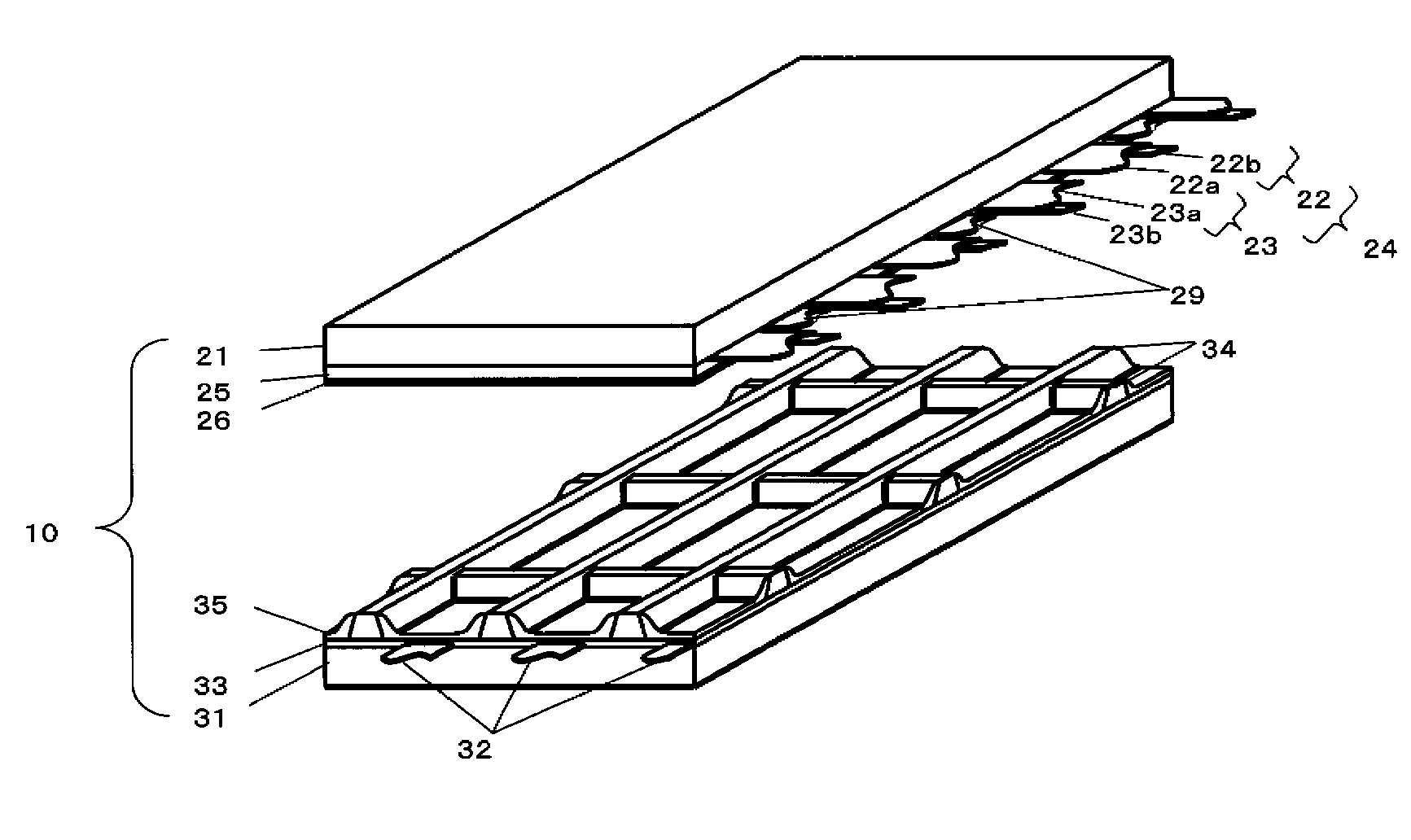
[0047] figure 1It is an exploded perspective view showing the structure of the panel 10 used in the first embodiment. A plurality of display electrode pairs 24 including scan electrodes 22 and sustain electrodes 23 are formed on front substrate 21 made of glass. In order to generate discharge and emit light in the discharge gap between scan electrode 22 and sustain electrode 23 forming display electrode pair 24, scan electrode 22 has a large-width transparent electrode 22a, and sustain electrode 23 also has a large-width transparent electrode 23a. Furthermore, bus electrodes 22b, 23b having a small width are stacked at positions away from the discharge gap above transparent electrodes 22a, 23a. Black stripes 29 for shielding light are arranged between adjacent display electrode pairs 24 . In addition, a dielectric layer 25 is formed to cover the scan electrodes 22 , the sustain electrodes 23 and the black stripes 29 , and a protective layer 26 is ...

no. 2 Embodiment approach

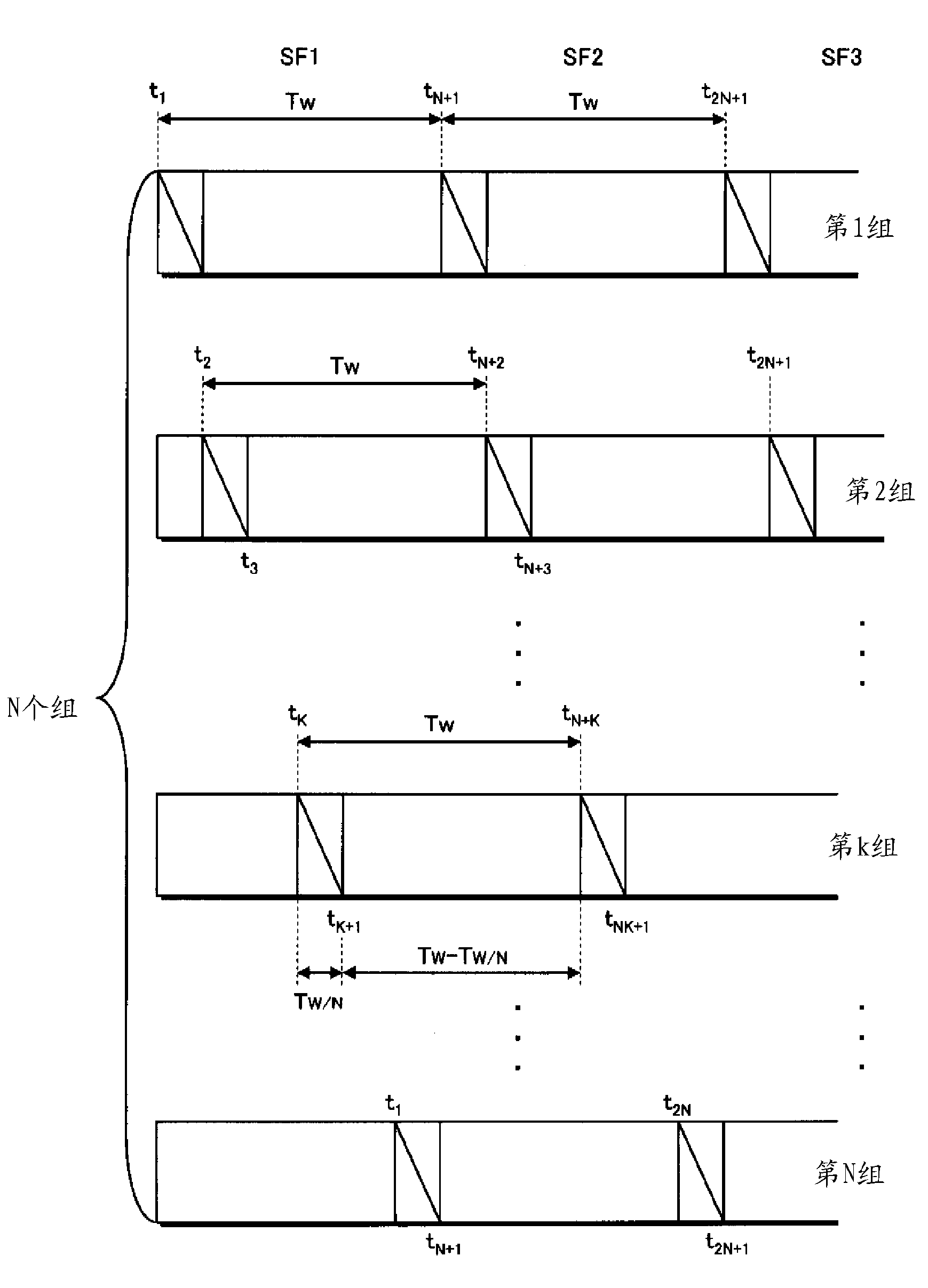
[0139] In the specific example of the above-mentioned first embodiment, the case where the number N of display electrode pairs is 2 is described. Next, the case where the number N of display electrode pairs is set to a larger value will be described.

[0140] In the present embodiment, write driving is performed by the one-shot scanning method similarly to the first embodiment, and the time of one field period is set to 16.7 ms. In addition, it is assumed that the time required for the initialization period is 500 μs, and the time required for the address operation per scan electrode is 0.7 μs. The time Tw required for all the scan electrodes to perform one address operation is 1512 μs. By performing the address operation continuously, 10 subfields can be ensured in one field, which is also the same as in the first embodiment.

[0141] However, in this embodiment, the number of sustain pulses applied in each subfield is set to '110', '81', '55', '33', '20', '11', '6', ' 4', '...


PUM


Abstract

Provided are a method for driving a PDP capable of ensuring the sufficient number of subfields to ensure the image quality even when being an ultra-high-definition panel, thereby enabling display with sufficient brightness, and a PDP device. One field period is divided into plural subfields each comprising a write period and a sustain period. Plural display electrode pairs are divided into plural (N) display electrode pair groups, and the subfield start timing is set for each of the display electrode pair groups. When the time required to perform one write operation in each of discharge cells of the entire panel is taken as Tw, the time length of the sustain period of each subfield of each display electrode pair group is set so as not to exceed Tw*(N-1) / N.

Description

technical field [0001] The invention relates to a driving method of a plasma display panel and a plasma display device, in particular to a driving method of a high-precision panel. Background technique [0002] In a typical AC surface discharge type panel among plasma display panels (hereinafter simply referred to as “panels”), many discharge cells (cells) are formed between a front substrate and a rear substrate that are arranged to face each other. [0003] A plurality of parallel display electrode pairs consisting of scan electrodes and sustain electrodes are formed on the front substrate, and a plurality of parallel data electrodes are formed on the back substrate. In addition, the front substrate and the rear substrate are arranged to face each other so that the display electrode pairs and the data electrodes intersect each other and are sealed, and a discharge gas is enclosed in the internal discharge space. Here, a discharge cell is formed at a portion where the disp...

Claims


Application Information

Patent Timeline
Patent Type & Authority Applications(China)
IPC IPC(8): G09G3/28G09G3/20G09G3/288G09G3/291G09G3/292G09G3/293G09G3/294G09G3/296G09G3/298
CPCG09G3/294G09G3/2927G09G3/2965G09G2310/0216G09G3/293G09G2310/0218G09G3/2022
Inventor 若林俊一小南智井土真澄新井康弘松下纯子牧野弘康
Owner PANASONIC CORP
Why Eureka
Try Eureka