System and method for wireless automatic meter reading

A wireless and meter-reading technology, applied in signal transmission systems, electrical signal transmission systems, information technology support systems, etc., can solve problems such as power consumption

Inactive Publication Date: 2003-05-28
BLUEMAX COMM
View PDF0 Cites 22 Cited by
  • Summary
  • Abstract
  • Description
  • Claims
  • Application Information

AI Technical Summary

Problems solved by technology

However, in this wireless system, it is necessary to continuously consume power for the meter that needs to update the accumulated data every now and then.

Method used


Image

  • System and method for wireless automatic meter reading
  • System and method for wireless automatic meter reading
  • System and method for wireless automatic meter reading

Examples


Embodiment Construction

[0047] Best Mode for Carrying Out the Invention

[0048] The present invention provides a wireless long-distance meter reading system for accumulative meters, the system includes: an image preprocessor, a processor for reading identification and data codes, a small chip with memory formed into one chip for processing a large amount of data The size of the optical text interpretation module, and a time controller with a sleep function to minimize power consumption.

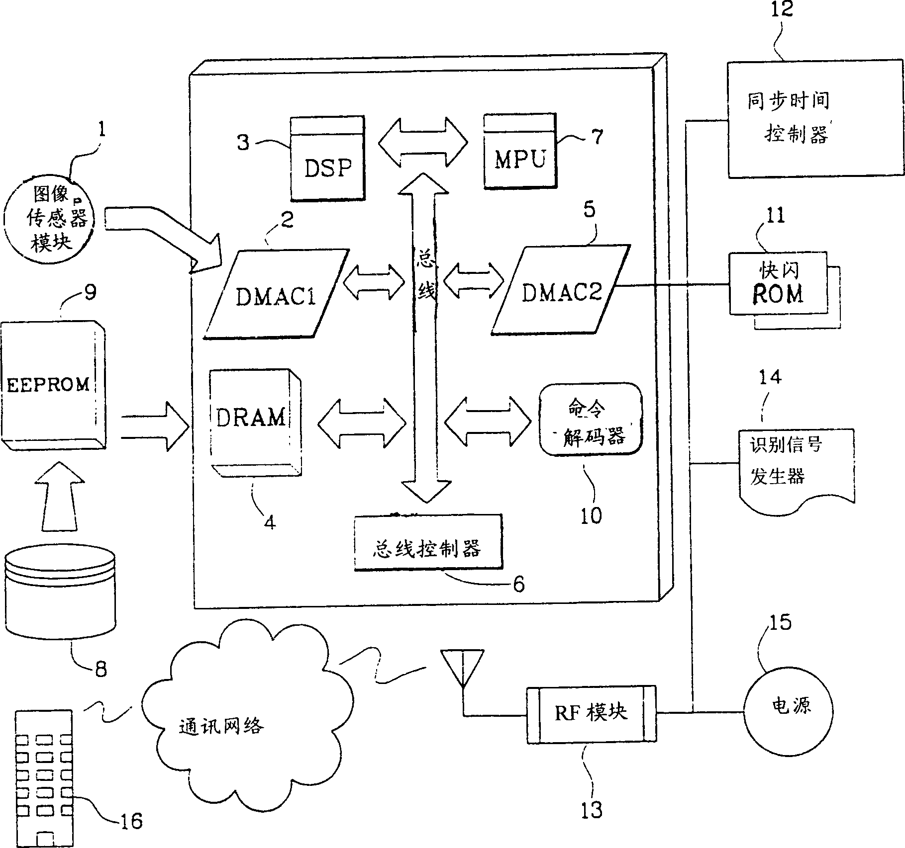
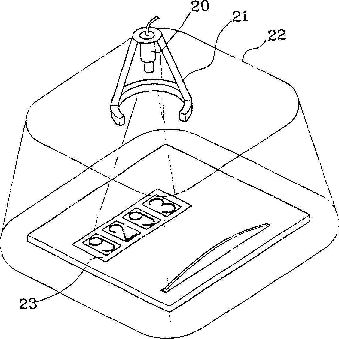
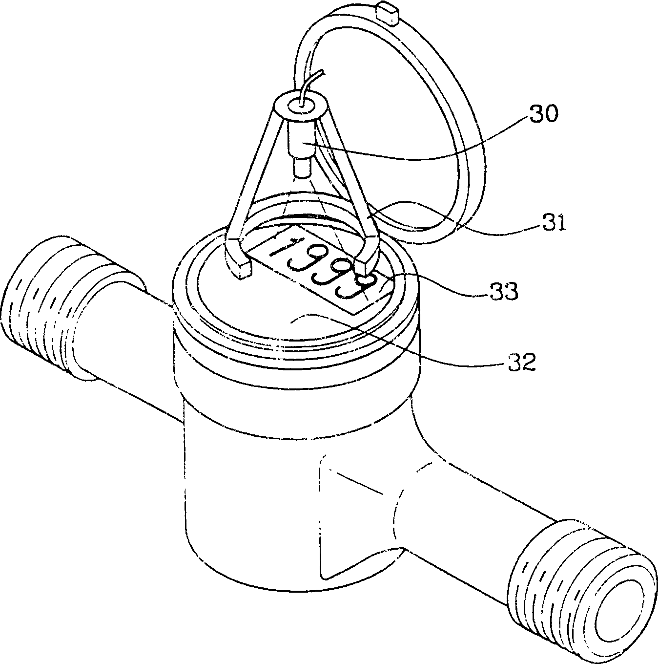
[0049] refer to figure 1 , which is a block diagram showing the structure of the system and method for wireless automatic meter reading according to the preferred embodiment of the present invention. As shown in the figure, the wireless remote meter reading system includes an image sensor module 1, which is fixedly arranged on a predetermined position on the top wall or bottom wall of the accumulative meter, so as to detect the digital image of the display part of the meter and Convert the detected image into an ...


PUM


Abstract

A system and method for wireless automatic meter reading which can wirelessly and remotely read integrated amounts of consumed electric power, water, gas and the like. An image sensor module (1) is installed in a predetermined portion of an integrating meter for picking up an image of a numeral displayed on a display of the integrating meter and converting the picked-up image into an electrical signal. A main processor unit (7) generates a numeric code corresponding to the numeral image. A radio frequency module (13) transmits the generated numeric code wirelessly to a meter reading center (16).

Description

technical field [0001] The present invention relates to a wireless automatic meter reading system and method capable of wirelessly and remotely reading the accumulated quantity of consumed electricity, water, gas, etc. Background technique [0002] Usually, in order to notify customers of the cost of water, electricity, and natural gas consumption, a meter reader must physically read the cumulative meter. That is, the meter reader must visually check the figure of a given meter, record the checked value by hand, subtract the previous month's figure from the recorded value, and then, based on the obtained figure and the accumulated quantity-fee table, give the user A billing notice. [0003] The disadvantage of this meter reading method is that it requires a lot of manpower, resulting in a lot of expenditure. Moreover, there may be many problems due to the mistakes of the meter reader, the absence of the owner or the refusal to read the meter. In addition, the meter readin...

Claims


Application Information

Patent Timeline
Patent Type & Authority Applications(China)
IPC IPC(8): G01D4/00G01D5/48G08C19/00G01R22/00G08C15/00G08C17/00G08C17/02G08C19/36H04Q9/04
CPCY02B90/243Y04S20/42Y02B90/247G08C19/36Y04S20/525G01D5/48H04Q9/04Y04S20/325Y02B70/346G08C17/02Y04S20/50Y02B90/242Y04S20/322Y02B90/246G01D4/004G01D4/008Y02B60/50G01R22/00Y02B70/34Y02B90/20Y04S20/30G08C19/00
Inventor 韩明国
Owner BLUEMAX COMM
Why Eureka
Try Eureka