Color wheel and projector using same
A projector and color wheel technology, applied in the field of projectors, to avoid carbonization, increase practicability and application surface effects
- Summary
- Abstract
- Description
- Claims
- Application Information
AI Technical Summary
Problems solved by technology
Method used
Image
Examples
no. 1 example
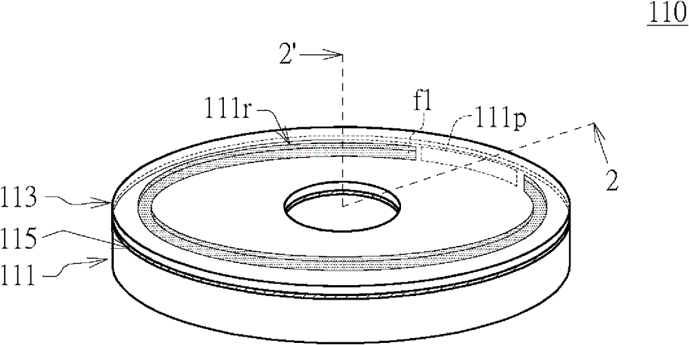
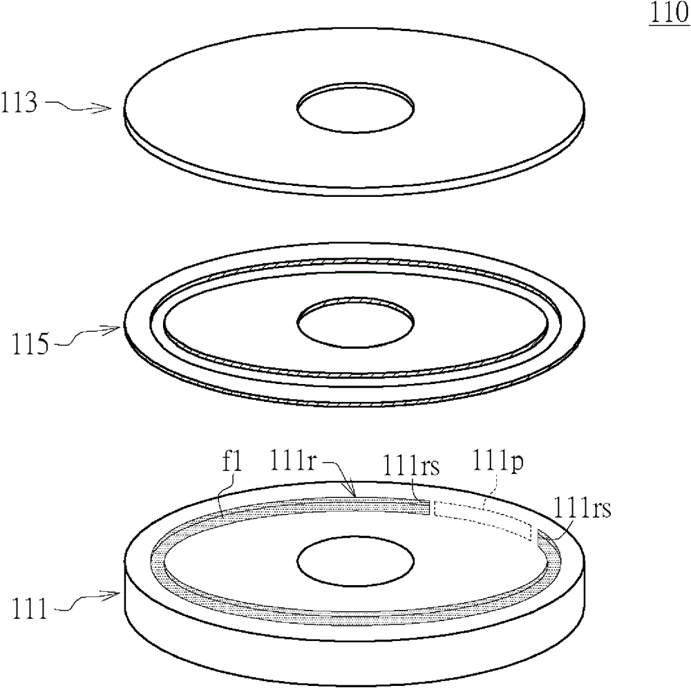
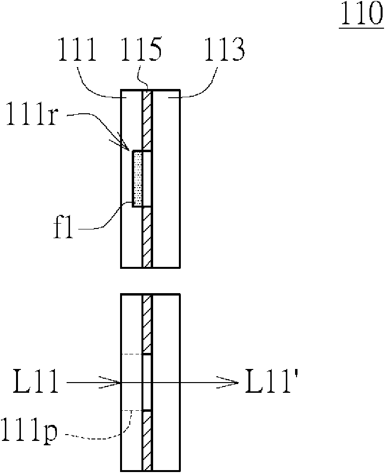
[0028] Please refer to Figure 1A , Figure 1B , Figure 2A and Figure 2B , Figure 1A A diagram showing the configuration of the color wheel according to the first embodiment of the present invention, Figure 1B draw Figure 1A Exploded diagram of the color wheel in , Figure 2A Draw along Figure 1A The cross-sectional view of the color wheel with the section line 2-2' in the light projected on the penetrating part, and Figure 2B shown in Figure 2A Cutaway view of light hitting the grooves after the color wheel in .
[0029] The color wheel 110 includes a main body 111 and a cover body 113 . The main body 111 has a groove 111r, and the groove 111r is used for accommodating the phosphor f1. The cover 113 is disposed on the main body 111 and covers the groove 111r.
[0030] In this embodiment, the groove 111r surrounds at least part of the periphery of the main body 111 . Here, it is illustrated that the groove 111r only surrounds a part of the periphery of the main...
no. 2 example
[0036] Please refer to Figure 3A and Figure 3B , which shows a schematic diagram of the first color light and the second color light generated by the color wheel of the transmissive projector according to the second embodiment of the present invention.
[0037] Figure 3A and Figure 3BThe structure of the color wheel 210 is similar to that of the color wheel 110 of the first embodiment, so the description is not repeated here. Since the color wheel 210 is used in the transmissive projector 200 , the material of the cover 213 of the color wheel 210 is a light-transmitting material, such as glass.
[0038] The transmissive projector 200 includes a color wheel 210 , a motor 220 , a digital micro-mirror device 230 , a lens 240 and a light source 250 . The motor 220 is connected to the color wheel 210 for driving the color wheel 210 to rotate. The light source 250 is used to generate the light L21.
[0039] When the light L21 is projected onto the penetrating portion 211p ...
no. 3 example
[0043] Please refer to Figure 4A and Figure 4B , which shows a schematic diagram of the first color light and the second color light generated by the color wheel of the reflective projector according to the third embodiment of the present invention.
[0044] Figure 4A and Figure 4B The structure of the color wheel 310 is similar to that of the color wheel 110 of the first embodiment, so the description is not repeated here. Since the color wheel 310 is used in the reflective projector 3((, the material of the cover 313 of the color wheel 310 is a light reflective material, such as an aluminum plate or a structure with a mirror surface.
[0045] The reflective projector 300 includes a color wheel 310 , a motor 320 , a digital micromirror device 330 , a lens 340 , a light source 350 and a dichroic mirror 360 . The motor 320 is connected to the color wheel 310 for driving the color wheel 310 to rotate. The light source 350 is used to generate the light L31a, which is gui...
PUM
 Abstract
Description
Claims
Application Information
 - R&D
- Intellectual Property
- Life Sciences
- Materials
- Tech Scout
- Unparalleled Data Quality
- Higher Quality Content
- 60% Fewer Hallucinations
Browse by: Latest US Patents, China's latest patents, Technical Efficacy Thesaurus, Application Domain, Technology Topic, Popular Technical Reports.
© 2025 PatSnap. All rights reserved.Legal|Privacy policy|Modern Slavery Act Transparency Statement|Sitemap|About US| Contact US: help@patsnap.com


