Toilet seat device

A technology for toilet seats and toilets, which is applied to water supply devices, seats or covers for toilets, flushing equipment with water tanks, etc., can solve problems such as increased use times, deterioration of relay mechanisms, and influences on the use period and frequency of toilet seat devices. , to achieve the effect of ensuring the exact implementation

Active Publication Date: 2011-06-08
PANASONIC CORP
View PDF1 Cites 8 Cited by
  • Summary
  • Abstract
  • Description
  • Claims
  • Application Information

AI Technical Summary

Problems solved by technology

If the toilet seat unit is used for a longer period of time or if it is used more frequently, the performance of the toilet seat unit itself will obviously gradually decrease
And, well-known, in the relay mechanism as representative earth leakage cut-off part, for example, if a large surge current is generated when the relay contact is closed, the possibility of welding becomes high, so the use of the toilet seat device The period and frequency of use do also affect the deterioration of the relay mechanism

Method used


Image

  • Toilet seat device
  • Toilet seat device
  • Toilet seat device

Examples


Embodiment approach 1

[0054] [Basic structure of toilet seat device]

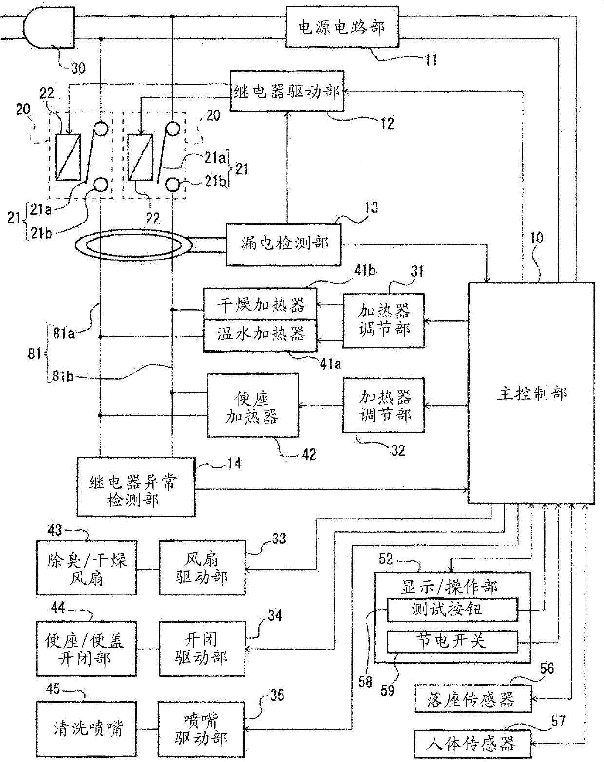
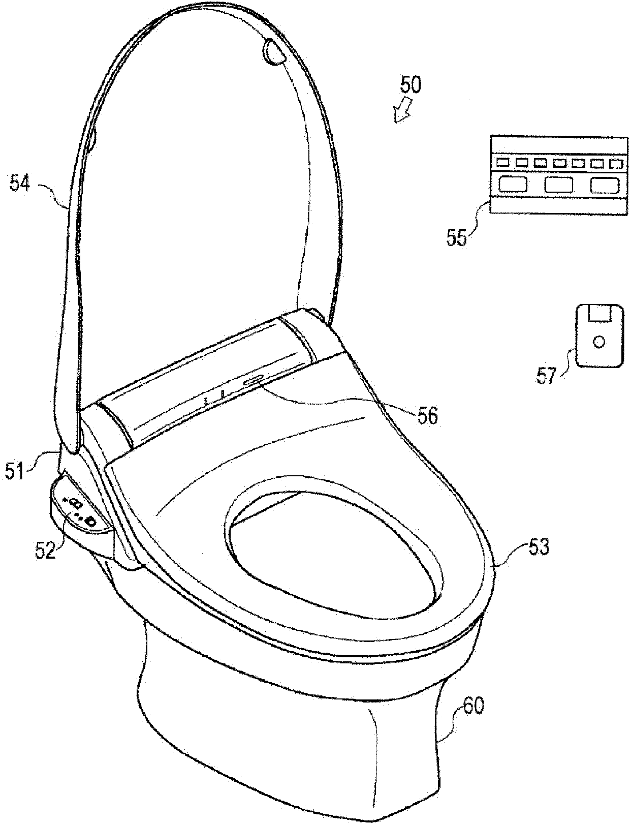
[0055] First, refer to figure 1 and figure 2 The specific structure of the toilet seat device which concerns on this embodiment is demonstrated. figure 1 It is a circuit diagram which shows an example of the electrical structure of the toilet seat apparatus concerning Embodiment 1 of this invention. figure 2 is showing figure 1 It is a schematic perspective view of an example of the external appearance of the toilet seat apparatus shown.

[0056] Such as figure 2 As shown, the toilet seat device 50 of this embodiment has a main body 51 , a display / operation unit 52 , a toilet seat 53 , a toilet cover 54 , a remote controller 55 , a seating sensor 56 , and a human body sensor 57 . The main body part 51, the toilet seat part 53, and the toilet cover part 54 of the toilet seat device 50 are assembled integrally, and are installed in the upper surface of the toilet bowl 60. As shown in FIG. Next, it demonstrates so that the...

Embodiment approach 2

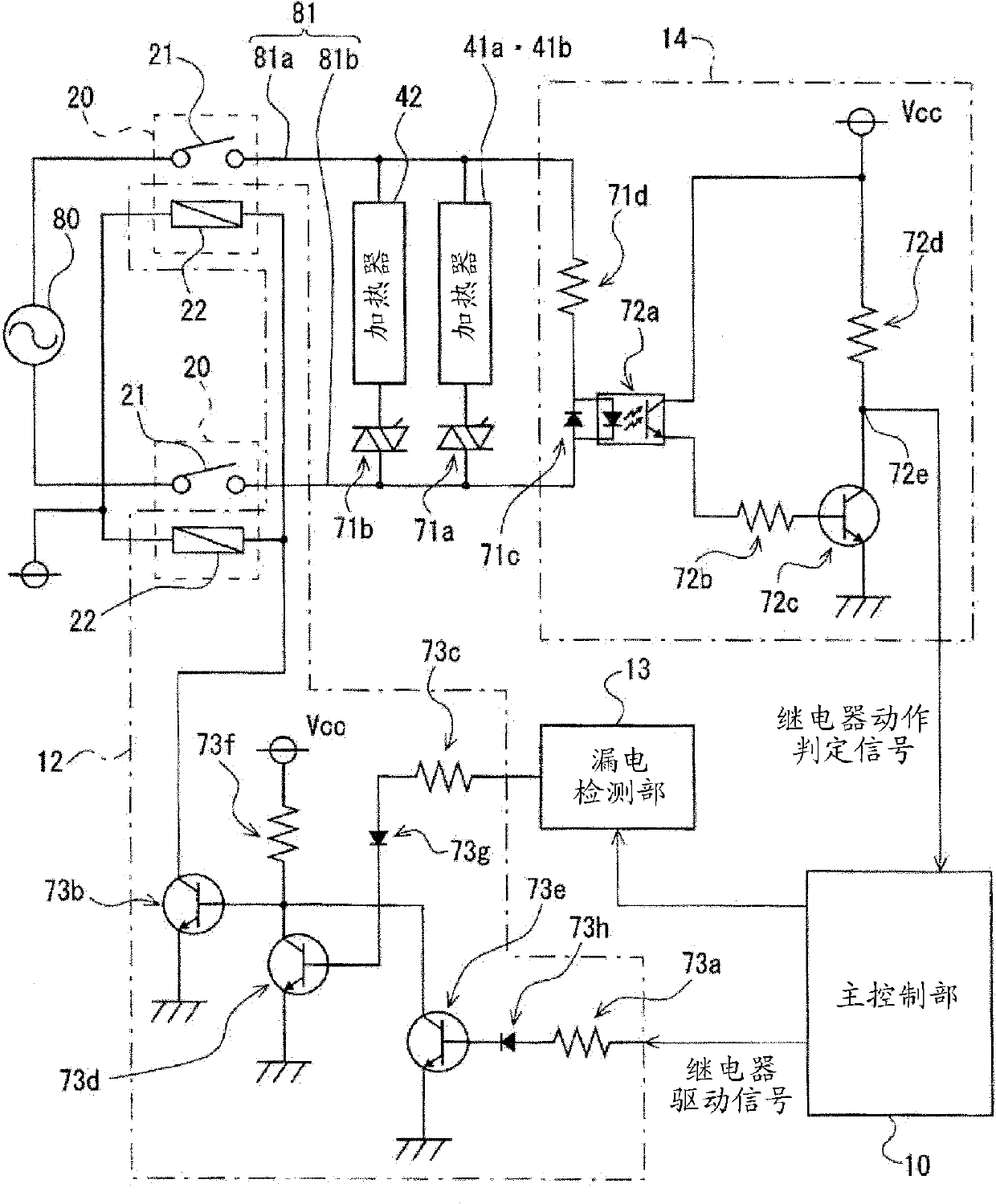
[0115] In Embodiment 1 described above, the main control unit 10 performs the following control: as a confirmation test of the leakage cut-off function, the relay mechanism 20 is tentatively opened and closed, and the presence or absence of an abnormality in the relay is detected by the relay abnormality detection unit 14. In this embodiment, it is also detected whether or not the control of the main control unit 10 itself is properly performed. That is, in the present invention, as described in the first embodiment, it may be configured to detect an abnormality of the relay as an abnormality of the earth leakage cut-off function, but it may also be configured so that the overall control of the toilet seat device 50 by the main control unit 10 (of course When some abnormality occurs in the control including the relay drive unit 12 and the relay mechanism 20, it is detected as an abnormality of the leakage cutoff function.


PUM


Abstract

Provided is a toilet seat device configured to automatically control a confirmation test of a leakage current cutting-off function in order to secure the execution of a suitable leakage current cutting-off operation at a leakage current time. A main control unit (10) of a toilet seat device regularly judges whether the toilet seat device is in a using condition or not by using results detected bya sitting sensor (56) or a human body sensor (57). When the main control unit judges that the toilet seat device is not in a using condition, the main control unit makes a relay contact point (21) ina relay mechanism (20) of a leakage current cutting-off unit experimentally open and close by a relay driving unit (12) and makes a relay abnormality detecting unit (14) detect the existence or non-existence of abnormalities. Hence, the minimum necessary degree of confirmation of the leakage current cutting-off function can be carried out at a non-using time of the toilet seat device, so that thetoilet seat device can be used after a normal cutting-off operation of the leakage current cutting-off unit has been confirmed and a suitable leakage current cutting-off operation can be secured.

Description

technical field [0001] The present invention relates to toilet seat devices such as a heated toilet seat and a warm water washing toilet seat, and more particularly to a toilet seat device having an electric leakage shutoff function and a function of checking abnormality of the electric leakage shutoff function. Background technique [0002] Toilet seat devices such as heated toilet seats and warm water toilet seats are hygienic products, so they are installed in an environment where water is used. However, toilet seat devices are also electrical products, so measures against electric leakage are required, so they have an electric leakage cutoff function. Specifically, for example, a structure in which an earth leakage breaker is integrated with a power plug for supplying power to a toilet seat device, or a structure in which an earth leakage interruption circuit is included in the toilet seat device main body, etc. are known. Generally, an earth leakage breaker or an earth ...

Claims


Application Information

Patent Timeline
Patent Type & Authority Applications(China)
IPC IPC(8): A47K13/30E03D9/08
CPCA47K13/30E03D5/10A47K13/305E03D9/08F24D19/1096H05B2203/029
Inventor 藤井真司近藤和也栗本由子
Owner PANASONIC CORP
Why Eureka
Try Eureka