Device for testing underwater high-speed object generated along with supercavity
What is Al technical title?
Al technical title is built by PatSnap Al team. It summarizes the technical point description of the patent document.
A test device and supercavitation technology, which is used in fluid dynamics tests, measuring devices, and testing of machine/structural components. problem, to achieve the effect of low cost, easy promotion and simple structure
Inactive Publication Date: 2012-05-23
ZHEJIANG SCI-TECH UNIV
View PDF1 Cites 0 Cited by
Summary
Abstract
Description
Claims
Application Information
AI Technical Summary
This helps you quickly interpret patents by identifying the three key elements:
Problems solved by technology
Method used
Benefits of technology
Problems solved by technology
This kind of equipment is relatively complicated and not suitable for popular use in the laboratory; and it generally can only maintain horizontal movement, but cannot complete the task of taking into account both water exit and water entry tests
Method used
Image
Click on the blue label to locate the original text in one second.
Reading with bidirectional positioning of images and text.
Examples
Embodiment Construction
[0021] The present invention will be further described below in conjunction with accompanying drawings and examples.
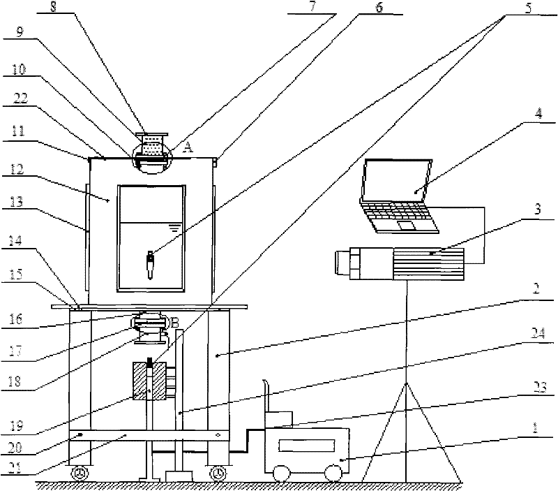
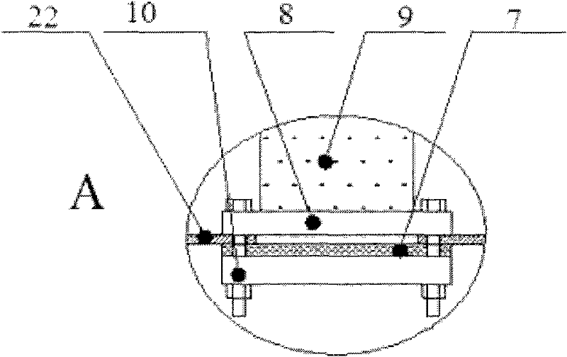
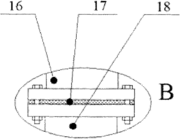
[0022] When carrying out the water exit test of high-speed objects, such as figure 1 As shown, the present invention includes a high-pressure gas source 1, a box support frame 2, a high-speed camera 3, an industrial computer 4, two diaphragms 7, 17, a safety interceptor 8, a water tank 12, a water tank cover 22, a flat panel 14, and a ball valve 18 , launch tube 19, reinforcement plate 21, gas duct 23, fastening plate 15, launch tube support frame 24; The upper end face of box body support frame 2 and the center of flat plate 14 have the through hole of equal diameter, and flat plate 14 lower end faces are the same The shaft is welded with a flange 16, the first diaphragm 17 and the ball valve 18 are sequentially installed downward on the flange 16, the launch tube 19 is connected with the launch tube support frame 24, the launch tube 19 is placed under the ba...
PUM
Abstract
The invention discloses a device for testing an underwater high-speed object generated along with supercavity, which comprises a high pressure gas source, a box body support rack, a high speed camera, an industrial personal computer, a membrane, a safety interceptor, a water tank, a water tank cover, a flat plate, a ball valve, a transmitting tube, a reinforced plate, a gas conduit, a fastening plate and a transmitting tube support rack. The object to be tested is driven and accelerated through nitrogen or helium released by the high pressure gas source and is then transmitted through the transmitting tube to enter the water tank filled with liquid, and when the object to be tested passes through the free face of the liquid from top to bottom and from bottom to top, a flow field having water inflow and water outflow generated along with the supercavity is generated. The generated supercavity flow has relatively clear inner and outer boundaries of a vapor / liquid two-phase flow, and with the help of various optical instruments and flow field visualization instruments, complex fluid dynamics behavior processes, such as the balance state of the gas inside vacuoles, the interaction of the free face and the supercavity, the instability of a vapor / liquid interface, the development of a turbulent boundary layer and the like, can be studied and comprehended.
Description
technical field [0001] The invention relates to a test device for fluid pressure in fluid mechanics, in particular to a test device for underwater high-speed objects accompanied by supercavitation. Background technique [0002] "Cavitation" is a common hydrodynamic phenomenon that occurs in regions of a liquid where the partial pressure is lower than the saturated vapor pressure at that temperature. As far as water is concerned, if the water temperature is not high, after reducing the pressure of the water surface to a certain critical value (the critical value is generally the saturated vapor pressure of the liquid) or accelerating the liquid flow to a certain speed, the microbubbles (gas) originally contained in the water will Nucleus) will expand rapidly, and then many obvious bubbles containing water vapor or other gases will be formed in the water. This is the common "cavitation phenomenon", and the generated bubbles are called "cavitation bubbles". When the water surf...
Claims
Application Information
Patent Timeline
Application Date:The date an application was filed.
Publication Date:The date a patent or application was officially published.
First Publication Date:The earliest publication date of a patent with the same application number.
Issue Date:Publication date of the patent grant document.
PCT Entry Date:The Entry date of PCT National Phase.
Estimated Expiry Date:The statutory expiry date of a patent right according to the Patent Law, and it is the longest term of protection that the patent right can achieve without the termination of the patent right due to other reasons(Term extension factor has been taken into account ).
Invalid Date:Actual expiry date is based on effective date or publication date of legal transaction data of invalid patent.