Rotary connecting device

A technology of rotating connection and rotating part, applied in the direction of flexible/rotatable wire connector, connection, three-pole connection, etc., can solve the problems of affecting signal transmission and easily damaged wires

Inactive Publication Date: 2011-06-15
HONG FU JIN PRECISION IND (SHENZHEN) CO LTD +1
View PDF5 Cites 17 Cited by
  • Summary
  • Abstract
  • Description
  • Claims
  • Application Information

AI Technical Summary

Problems solved by technology

If the number of rotations and times is too large or the angle is too large, the wire will be easily broken, which will affect the transmission of the signal

Method used


Image

  • Rotary connecting device
  • Rotary connecting device
  • Rotary connecting device

Examples


Embodiment Construction

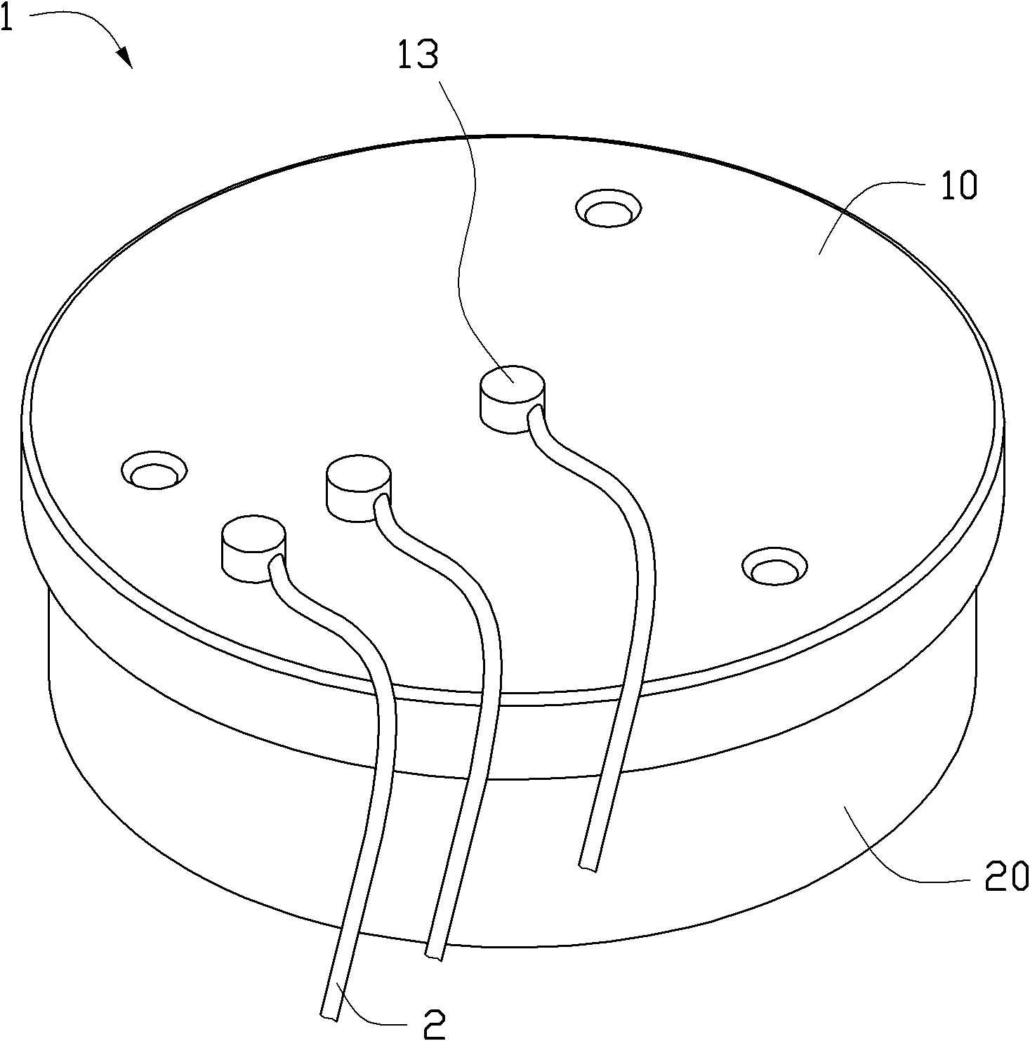
[0012] see figure 1 , the rotating connection device 1 includes a first rotating part 10 and a second rotating part 20 respectively connected with wires 2 , wherein the second rotating part 20 can rotate around the first rotating part 10 .

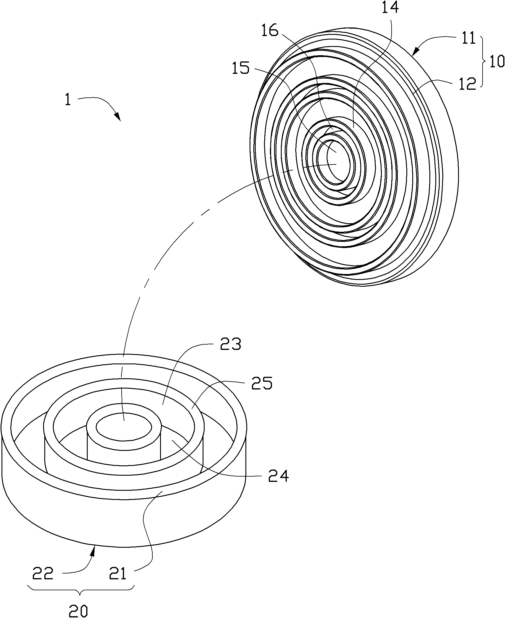
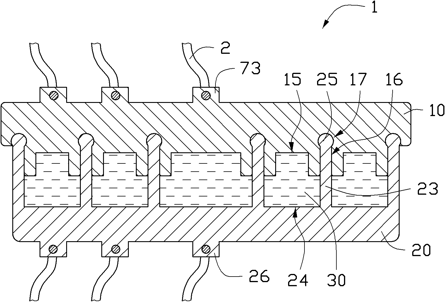
[0013] Please also refer to figure 2 , which is an exploded view of the rotary connection device 1 . The first rotating part 10 includes a first end surface 11 and a second end surface 12 opposite to each other. A plurality of conductive columns 13 are disposed on the first end surface 11 , and the plurality of conductive columns 13 are located in different radius areas relative to the center of the first rotating portion 10 . In this embodiment, the number of the conductive pillars 13 is three. A plurality of fixing portions 14 are disposed on the second end surface 12 . The fixing portions 14 are ring-shaped, and each bottom portion forms a conductive portion 15 . In this embodiment, the plurality of fixing portions 14 are concentri...


PUM


Abstract

The invention provides a rotary connecting device comprising a first rotary part and a second rotary part, wherein the first rotary part can rotate relative to the second rotary part. A same number of conducting poles are respectively arranged on opposite end surfaces of the first rotary part and the second rotary part. The first rotary part is projectedly provided with a plurality of ring-shaped fixing parts. Each fixing part is provided with an accommodating groove. The second rotary part is provided with a plurality of stopper rings corresponding to the plurality of ring-shaped fixing parts. After the stopper rings are clamped in the accommodating grooves, the fixing parts and the stopper rings are communicated to form a plurality of mutually isolated cavities. The tail end of each accommodating grooves is provided with a stopper groove. The tail end of each stopper rings is provided with a stopper part correspondingly. The stopper part is clamped in the stopper groove, so that the first rotary part and the second rotary part are fixed relative to each other. Conducting fluid is stored in each cavity. Each pair of positive conducting pole and negative conducting pole are conducted by the conducting fluid.

Description

technical field [0001] The invention relates to a rotary connection device for connecting wires. Background technique [0002] In many mechatronic devices, a rotating mechanism is provided, which includes a first rotating part and a second rotating part. Wherein, the second rotating part can rotate around the first rotating part. At the same time, the rotating mechanism needs to be provided with some wires so that signals can be transmitted between the first rotating part and the second rotating part, so as to control the rotation of the first rotating part and the second rotating part. However, when the second rotating part rotates around the first rotating part, the wire disposed therebetween may be wound as the second rotating part rotates. If the number of rotations and times is too large or the angle is too large, the wire will be easily broken, which will affect the transmission of the signal. Contents of the invention [0003] In view of this, it is necessary to ...

Claims


Application Information

Patent Timeline
Patent Type & Authority Applications(China)
IPC IPC(8): H01R35/00H01R3/08
CPCH01R39/64H01R2105/00
Inventor 赖金石
Owner HONG FU JIN PRECISION IND (SHENZHEN) CO LTD
Why Eureka
Try Eureka