Method for arranging in-situ leaching hole drilling filter

An arrangement method and filter technology, which are applied to earth-moving drilling, mining fluids, wellbore/well components, etc., can solve the problems of low uranium concentration, ineffective leaching of uranium metal, and long leaching period, and improve the uranium content. Effect

Inactive Publication Date: 2011-06-22
BEIJING RESEARCH INSTITUTE OF CHEMICAL ENGINEERING AND METALLURGY
View PDF10 Cites 12 Cited by
  • Summary
  • Abstract
  • Description
  • Claims
  • Application Information

AI Technical Summary

Problems solved by technology

In most cases, the permeability of the ore bed is less than that of the surrounding rock, and most of the leaching solution that enters the ore bed through the liquid injection drilling filter does not infiltrate the ore bed or contact the uranium ore, so the ore bed cannot be effectively leached The uranium metal in the leach solution is low in uranium concentration and the leaching cycle is long

Method used


Image

  • Method for arranging in-situ leaching hole drilling filter
  • Method for arranging in-situ leaching hole drilling filter
  • Method for arranging in-situ leaching hole drilling filter

Examples


Embodiment 1

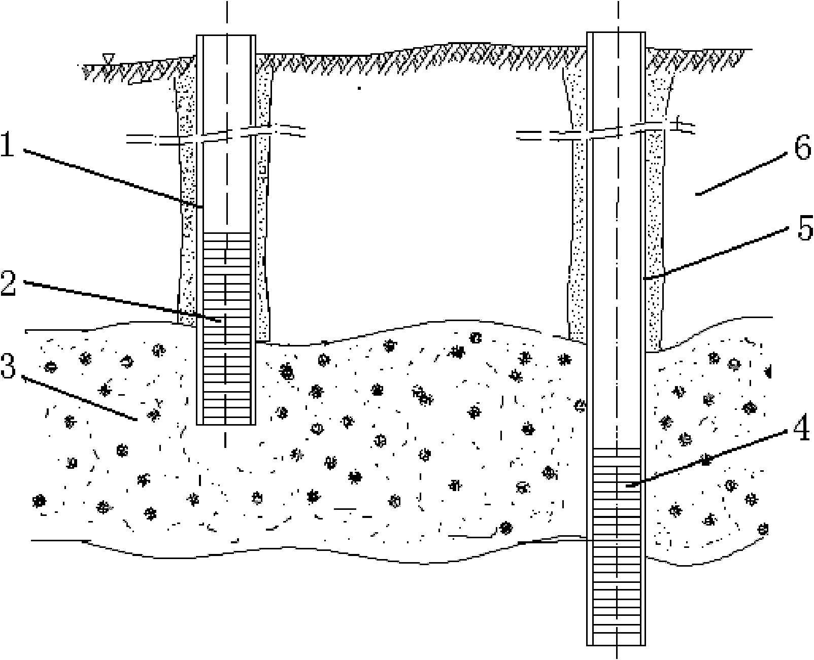
[0017] Such as figure 2 As shown, a kind of in-situ leaching borehole filter arrangement method described in the present invention is used in the production of an in-situ leaching uranium ore. When the uranium ore is a single vein, there is only one layer of uranium ore layer 3, and both the upper and lower layers of the uranium ore layer 3 are non-mineral layers 6.

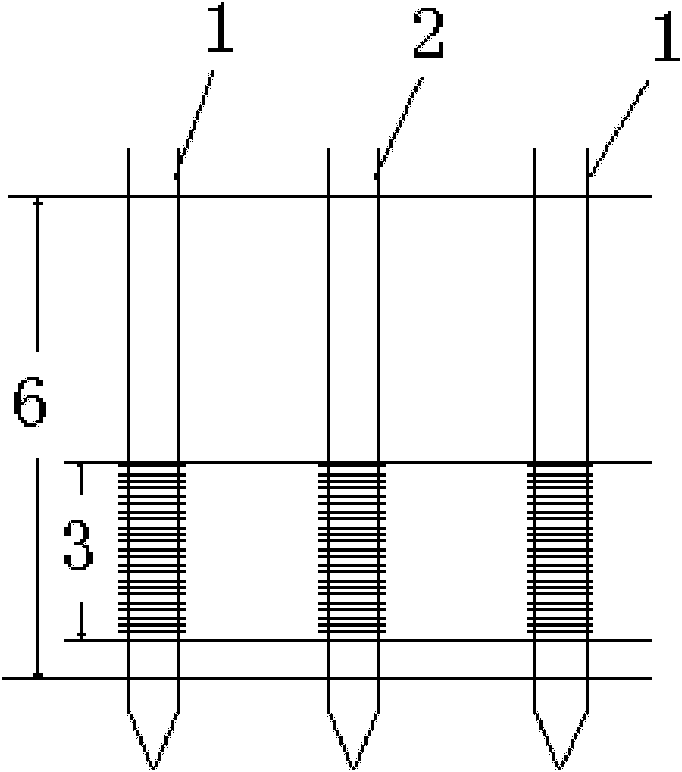
[0018] There are 4 drilling holes for pumping liquid and 9 drilling holes for liquid injection. Lower the liquid pumping borehole casing 5 in the liquid pumping borehole; each of the liquid injection borehole casings 1 is provided with a liquid injection borehole filter 2, and each liquid suction borehole casing 5 is All are provided with a suction drilling filter 4.

[0019] The length of the liquid injection drilling filter 2 that is located in the liquid injection drilling casing 1 is 3 / 4 of the thickness of the uranium ore layer 3, and the bottom end of the liquid injection drilling filter 2 is positioned ...

Embodiment 2

[0025] The difference from Example 1 is:

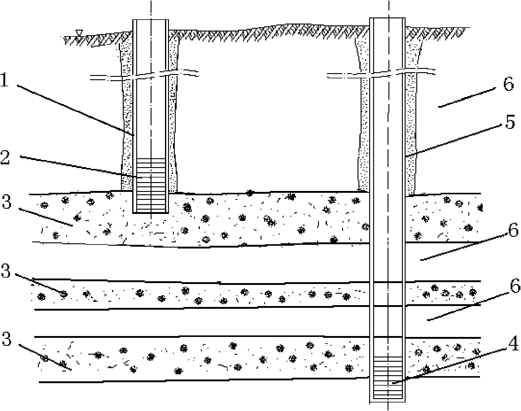
[0026] The bottom end of the liquid injection drilling filter 2 is located at the top of the uranium ore layer 3 , and the top of the liquid injection drilling filter 2 extends upwards to the non-ore layer 6 .

[0027] The top of the liquid suction borehole filter 4 is located at the bottom of the uranium ore layer 3 , and the bottom end of the liquid suction borehole filter 4 extends downward to the non-mineral layer 6 .

Embodiment 3

[0029] The difference from Example 1 is:

[0030] The length of the liquid injection drilling filter 2 arranged in the liquid injection drilling casing 1 is 4 / 5 of the thickness of the uranium ore layer 3, and the bottom end of the liquid injection drilling filter 2 is located at 1 / 3 of the thickness of the uranium ore layer 3 , the top of the liquid injection drilling filter 2 extends upwards to the non-mineral layer 6 .

[0031] The length of the liquid suction borehole filter 4 is 4 / 5 of the thickness of the uranium ore layer 3, the top of the liquid suction borehole filter 4 is located at 2 / 3 of the thickness of the uranium ore layer 3, and the bottom of the liquid suction borehole filter 4 The end extends down to the non-mine layer 6.


PUM


Abstract

The invention relates to a method for arranging an in-situ leaching hole drilling filter. If a uranium ore has a single vein, the length of a liquid injection hole drilling filter is three fourths to four fifths the thickness of the uranium ore layer, the bottom of the liquid injection hole drilling filter is positioned between the top part and the middle part of the uranium ore layer, the top of the liquid injection hole drilling filter is extended to a non ore layer, the length of an extraction hole drilling filter is three fourths to four fifths the thickness of the uranium ore layer, the top of the extraction hole drilling filter is positioned between the middle part and the bottom of the uranium ore layer and the bottom of the extraction hole drilling filter is extended to the non ore layer; and if the uranium ore has multiple veins, the length of the liquid injection hole drilling filter is three fourths to four fifths the thickness of the topmost uranium ore layer, the bottom of the liquid injection hole drilling filter is positioned between the top part and the middle part of the topmost uranium ore layer, the top of the liquid injection hole drilling filter is extended to the non ore layer, the length of the extraction hole drilling filter is three fourths to four fifths the thickness of the lowest uranium ore layer, and the top of the extraction hole drilling filter is positioned between the middle part and the bottom of the lowest uranium ore layer and the bottom of the extraction hole drilling filter is extended downward to the non ore layer. By the method, leaching liquid can flow directionally, the full and effective contact between the leaching liquid and ore is guaranteed, and the uranium concentration of the leaching liquid is improved.

Description

technical field [0001] The invention relates to a drilling construction technique for in-situ leaching for uranium mining, in particular to a method for arranging filters in an in-situ leaching drilling. Background technique [0002] The in-situ leaching borehole filter is the throat of the in-situ leaching uranium mining process, and it is the only channel for the leaching liquid to enter the ground and the leaching liquid to be pumped out of the surface. Such as figure 1 As shown, the original in-situ leaching technology requires that the installation length of the borehole filter be greater than or equal to the thickness of the ore seam, and it should be lowered directly against the ore seam, and its installation position is located in the ore seam. In most cases, the permeability of the ore bed is less than that of the surrounding rock, and most of the leaching solution that enters the ore bed through the liquid injection drilling filter does not infiltrate the ore bed ...

Claims


Application Information

Patent Timeline
Patent Type & Authority Applications(China)
IPC IPC(8): E21B43/00E21B43/02
Inventor 谭亚辉胡柏石张斌姜岩
Owner BEIJING RESEARCH INSTITUTE OF CHEMICAL ENGINEERING AND METALLURGY
Why Eureka
Try Eureka