
Automatic detection control device for heavy rammer

An automatic detection and control device technology, applied in hoisting devices, clockwork mechanisms, roads, etc., can solve problems affecting the working efficiency of dynamic compaction machines, cumbersome operation methods, and increased operating costs, so as to save manpower and material costs, The effect of convenient operation and simple structure

Inactive Publication Date: 2012-07-11
SHANGHAI SANY TECH
View PDF0 Cites 2 Cited by
  • Summary
  • Abstract
  • Description
  • Claims
  • Application Information

AI Technical Summary

Problems solved by technology

However, the above operation method is relatively cumbersome, and manual hooking is required every time; on the other hand, in the decoupling mode, the wire rope on the dynamic tamping machine is prone to disorder.
This undoubtedly affects the operating efficiency of the dynamic compaction machine to a certain extent and increases the operating cost.

Method used


Image

  • Automatic detection control device for heavy rammer
  • Automatic detection control device for heavy rammer

Examples


Embodiment Construction

[0012] The present invention will be described in further detail below in conjunction with the accompanying drawings.

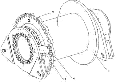
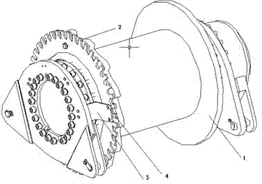
[0013] In order to realize that the dynamic tamping machine works in the non-decoupling mode, it is necessary to monitor the length of the steel wire rope in real time, and to perform timely automatic braking when the length is set. figure 1 It is a structural schematic diagram of the automatic detection control device of the dynamic compaction machine of the present invention. It can be seen from the figure that the automatic detection control device of the dynamic compaction machine in the present invention includes a high-frequency detection proximity switch (not shown in the figure), a gear ring 2 and a controller (not shown in the figure). Wherein, the gear ring 2 is installed on the side of the hoist drum 1, and the high-frequency detection proximity switch is installed on the outside of the drum 1, and is close to the gear ring 2, so as to ensure that ...


PUM


Abstract

The invention provides an automatic detection control device for a heavy rammer, which comprises a high-frequency detection proximity switch, a gear ring and a controller, wherein the gear ring is arranged on the side face of a winding drum of a winding engine; the high-frequency detection proximity switch is close to the gear ring and is arranged on the outer side of the winding drum; and the controller is connected to the high-frequency detection proximity switch. The automatic detection control device for the heavy rammer detects the rotation speed of the winding drum by using the high-frequency detection proximity switch and consequently calculates the released length of a steel wire rope on the heavy rammer so as to realize the automatic brake of a pounder falling freely with a load.The structure of the device is simple and the operation of the device is convenient; therefore, labor cost and material cost are saved considerably, and the working efficiency of the heavy rammer is improved effectively.

Description

technical field [0001] The invention relates to the technical field of dynamic compaction machines, in particular to an automatic detection and control device for dynamic compaction machines. Background technique [0002] During the operation of the dynamic tamping machine, it is necessary to frequently carry out the operations of hooking the tamper, lifting the tamper to a certain height and uncoupling and dropping the tamper. In the specific operation, first, the operation of the hook needs to be completed manually; then, the rammer is lifted to the set height, and the wire rope is tightened; finally, the rammer breaks away from the hook and falls freely. However, the above-mentioned operation method is relatively cumbersome, and manual hooking is required every time; on the other hand, under the decoupling mode, the steel wire rope on the dynamic tamping machine is prone to disordered ropes. This undoubtedly affects the operating efficiency of the dynamic compaction ...

Claims


Application Information

Patent Timeline
Patent Type & Authority Patents(China)
IPC IPC(8): B66D1/40E02D3/046E01C19/34
Inventor 罗顺国赵伟
Owner SHANGHAI SANY TECH
Learn More