Braking method for belt conveyor

A technology of belt conveyor and brake block, which is applied in the direction of conveyor, transportation and packaging, etc., can solve the problems of expensive, complicated structure, time-consuming and laborious, and achieve the effect of expanding the distance

Active Publication Date: 2020-08-11
山东长江粮油仓储机械有限公司 +1
View PDF7 Cites 2 Cited by
  • Summary
  • Abstract
  • Description
  • Claims
  • Application Information

AI Technical Summary

Problems solved by technology

[0002] When the existing belt conveyor brakes, it usually pulls the brake switch manually or additionally installs an electric or magnetic brake device on the transmission shaft. The manual switch method requires manual guarding or walking to the brake switch to start the brake. Switching is time-consuming and labor-intensive, and there are potential safety hazards. Electric or magnetic braking devices are usually controlled remotely, which is more convenient, but the additional structure is complicated and expensive. At the same time, the above-mentioned braking methods cannot accurately control the timing of braking.

Method used


Image

  • Braking method for belt conveyor
  • Braking method for belt conveyor
  • Braking method for belt conveyor

Examples


Embodiment 1

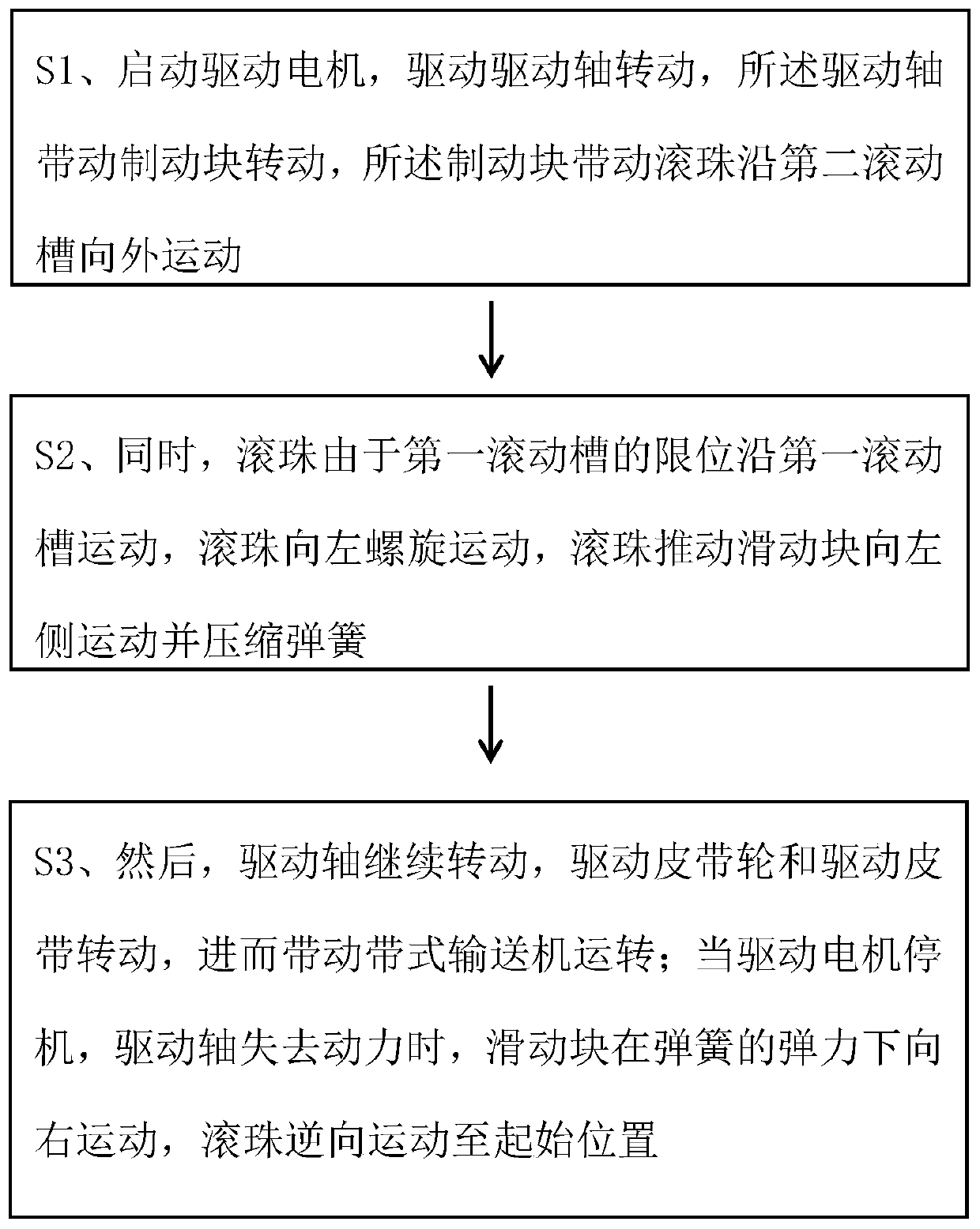
[0031] A braking method for a belt conveyor, comprising the steps of:

[0032] S1. Start the drive motor to drive the drive shaft to rotate, the drive shaft drives the brake block to rotate, and the brake block drives the balls to move outward along the second rolling groove.

[0033] S2. At the same time, due to the limit of the first rolling groove, the ball moves along the first rolling groove, the ball spirally moves to the left, and the ball pushes the sliding block to move to the left and compresses the spring.

[0034] S3. Then, the drive shaft continues to rotate, the drive pulley and the drive belt rotate, and then drives the belt conveyor to run; when the drive motor stops and the drive shaft loses power, the sliding block moves to the right under the elastic force of the spring, and the ball moves in reverse to starting point.

[0035] The step S2 also includes: when the ball moves to the end of the first rolling groove and the second rolling groove, the sliding ke...

Embodiment 2

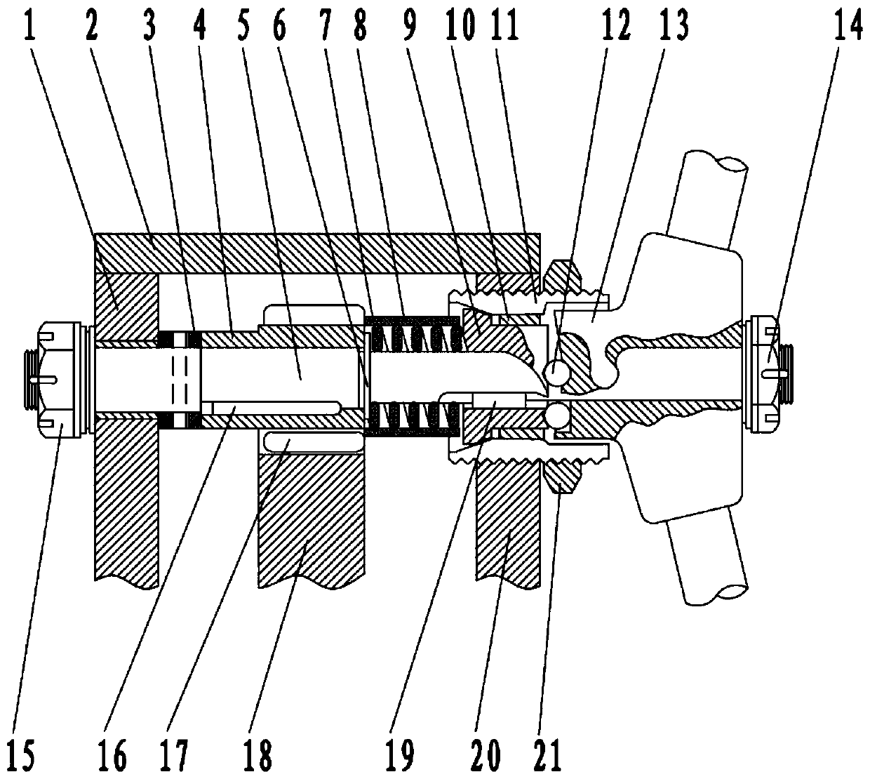
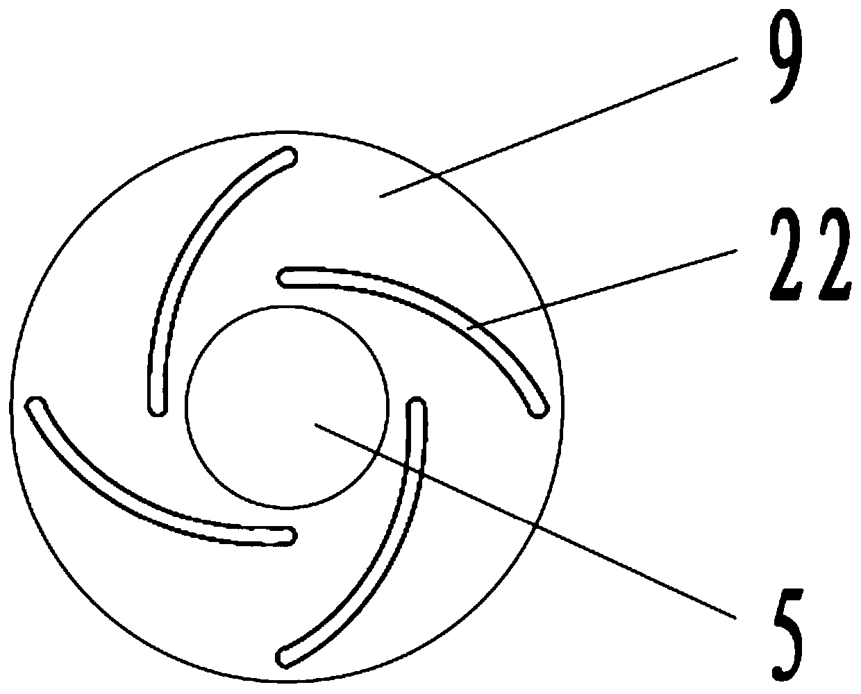
[0039] Such as Figure 2-4 As shown, a braking device for a belt conveyor includes: a drive shaft 5, which is used to drive a pulley 17, and then drives a belt conveyor; a sliding block 9, which is used for braking the drive shaft 5; The structure is used to control the sliding block 9 to move between the braking position and the non-braking position.

[0040] The left end of the drive shaft 5 is rotated on the first support 1 through a bearing, and the left end of the drive shaft 5 is limited in the axial direction by the first fastening nut 15 and the limit sleeve 3. The right side of the shaft sleeve 3 is abutted against a transmission shaft sleeve 4 .

[0041] The brake structure includes a spring washer 6, a spring 7, a sliding block 9, a brake sleeve 11, a ball 12 and a brake block 13, and the spring washer 6 is arranged on the right side of the transmission sleeve 4, The right side of the spring washer 6 abuts against a spring 7, the right side of the spring 7 abuts a...

Embodiment 3

[0051] Such as Figure 2-4 As shown, a braking device for a belt conveyor includes: a drive shaft 5, which is used to drive a pulley 17, and then drives a belt conveyor; a sliding block 9, which is used for braking the drive shaft 5; The structure is used to control the sliding block 9 to move between the braking position and the non-braking position.

[0052] The left end of the drive shaft 5 is rotated on the first support 1 through a bearing, and the left end of the drive shaft 5 is limited in the axial direction by the first fastening nut 15 and the limit sleeve 3. The right side of the shaft sleeve 3 is abutted against a transmission shaft sleeve 4 .

[0053] The brake structure includes a spring washer 6, a spring 7, a sliding block 9, a brake sleeve 11, a ball 12 and a brake block 13, and the spring washer 6 is arranged on the right side of the transmission sleeve 4, The right side of the spring washer 6 abuts against a spring 7, the right side of the spring 7 abuts a...


PUM


Abstract

The invention relates to a braking method for a belt conveyor. The braking method comprises the following steps that S1, a driving motor is started to drive a driving shaft to rotate, the driving shaft drives a brake block to rotate, and the brake block drives rolling balls to move outwards along second rolling grooves; S2, the rolling balls move along first rolling grooves due to the limiting ofthe first rolling grooves, the rolling balls spirally move to the left, and the rolling ball pushes a sliding block to move to the left side and compresses a spring; and S3, the driving shaft continues to rotate, a belt pulley and a driving belt are driven to rotate, and then the belt conveyor is driven to operate; and when the driving motor is stopped, the driving shaft loses power, the sliding block moves to the right under the elastic force of the spring, and the rolling balls move reversely to starting positions. According to the braking method, braking of the belt conveyor without additional power is carried out and reverse rotation of the belt conveyor is prevented by cooperation of the spring, the sliding block, a brake sleeve, the rolling balls and the brake block, and the brakingoccasion can be accurately controlled.

Description

technical field [0001] The invention relates to the technical field of belt conveyors, in particular to a braking method for belt conveyors. Background technique [0002] When the existing belt conveyor brakes, it usually pulls the brake switch manually or additionally installs an electric or magnetic brake device on the transmission shaft. The manual switch method requires manual guarding or walking to the brake switch to start the brake. Switching is time-consuming and labor-intensive, and there are potential safety hazards. Electric or magnetic braking devices are usually controlled remotely, which is more convenient, but the additional structure is complex and expensive. At the same time, the above-mentioned braking methods cannot accurately control the timing of braking. Contents of the invention [0003] The purpose of the present invention is to address the above problems, providing a braking method for belt conveyors with a simple structure and capable of accuratel...

Claims


Application Information

Patent Timeline
Patent Type & Authority Applications(China)
IPC IPC(8): B65G23/26
CPCB65G23/26
Inventor 朱箫笛
Owner 山东长江粮油仓储机械有限公司
Why Eureka
Try Eureka