Electronic component mounting device

A technology for installing electronic components and electronic components, which is applied in the direction of electrical components, electrical components, etc., can solve problems such as difficulty in preventing misinstallation, and achieve the effects of avoiding installation actions, realizing rapidity, and realizing installation work efficiency

Active Publication Date: 2015-09-16
JUKI CORP
View PDF5 Cites 0 Cited by
  • Summary
  • Abstract
  • Description
  • Claims
  • Application Information

AI Technical Summary

Problems solved by technology

[0004] However, in electronic parts, there are many cases where the appearance characteristics are roughly the same but the types of parts are different, and there is a limit to preventing incorrect mounting according to the appearance characteristics.
In addition, depending on the electronic component, there may be polarity. If the component has a symmetrical shape, it is difficult to judge whether the electronic component picked up by the mounting head is held in the correct direction of the polarity based on the appearance characteristics, and it is difficult to prevent the error of the wrong polarity. Install

Method used


Image

  • Electronic component mounting device
  • Electronic component mounting device
  • Electronic component mounting device

Examples


Embodiment approach

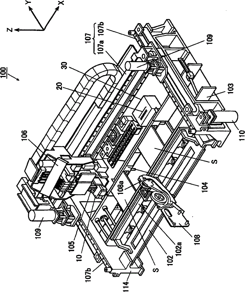
[0047] based on Figure 1 to Figure 7 , to describe embodiments of the invention. figure 1 It is a perspective view of the electronic component mounting apparatus 100 which concerns on this embodiment. Hereinafter, as shown in the drawing, two directions perpendicular to each other on a horizontal plane are referred to as an X-axis direction and a Y-axis direction, respectively, and a vertical direction perpendicular to them is referred to as a Z-axis direction.

[0048]The electronic component mounting apparatus 100 mounts various electronic components C on the substrate S, such as figure 1 As shown, there is: a component supply part, which is composed of a feeder storage part 102 as a setting part, and the feeder storage part 102 holds a plurality of them in parallel (in figure 1 Only one is shown in the figure) an electronic component feeder 108 as a component supply device, which supplies electronic components C to be mounted; a substrate conveying unit 103, which convey...


PUM


Abstract

The invention relates to an electronic component mounting device capable of preventing the mis-installation of electronic elements and improving the productivity. The front end portion of the suction nozzle of the device is an insulator. The device comprises a storage part for storing the installation data, a contact part arranged in the transferring area of the moving mechanism, a measurement apparatus and a motion control unit. The installation data includes the sequence and the electrical characteristic of the electronic elements of the suction nozzles boarded on the boarding head. The control part is equipped with a plurality of pairs of detectors capable of being electrically connected with the two electrodes of the electronic elements. The measurement apparatus measures the electrical characteristic of the electronic elements. The measurement results measured by the measurement apparatus is compared with the installation data by the motion control unit, so that the matching ability of the electrical characteristic is determined. The non-matching condition is then informed. The plurality of pairs of detectors are arranged in a row when the interval of the detectors is in consistent with the distance between the centers of the suction nozzles.

Description

technical field [0001] The present invention relates to a technique for reducing erroneous mounting in an electronic component mounting device. Background technique [0002] The electronic component mounting apparatus has: a component supply unit that supplies various electronic components; a holding mechanism that holds the conveyed substrate at a predetermined component mounting work position; and a mounting head that absorbs each electronic component from the component supply unit. , and installed on each target installation position of the substrate. In addition, the control device of the above-mentioned electronic component mounting apparatus controls the operation of the mounting head and performs the mounting operation of the electronic component on the substrate with reference to the mounting data, wherein the type of component is preset for each electronic component to be mounted. , electrical characteristics, where the components are picked, where they are mounted...

Claims


Application Information

Patent Timeline
Patent Type & Authority Patents(China)
IPC IPC(8): H05K13/04H05K13/08
Inventor 高桥大助柴田毅高久常雄佐藤佳孝小林仁麻生文彦藤原正人
Owner JUKI CORP
Why Eureka
Try Eureka