
Centrifuge and centrifuge rotor for the same

By adopting the design of the loose support and disengagement mechanism of the upper and lower drum parts in the centrifuge, the self-emptying of the centrifugal drum and the sealing performance at high speeds are realized, which solves the problems of solid material clogging and load increase in the existing technology, and improves the efficiency of the centrifuge. improve the efficiency and service life of the equipment.

Inactive Publication Date: 2011-07-13
BOLL & KIRCH FILTERBAU GMBH
View PDF1 Cites 6 Cited by
  • Summary
  • Abstract
  • Description
  • Claims
  • Application Information

AI Technical Summary

Problems solved by technology

As the working time increases, the entire inner space of the centrifugal drum is filled and the separation capacity decreases

Method used


Image

  • Centrifuge and centrifuge rotor for the same
  • Centrifuge and centrifuge rotor for the same
  • Centrifuge and centrifuge rotor for the same

Examples


Embodiment Construction

[0018] specific implementation plan

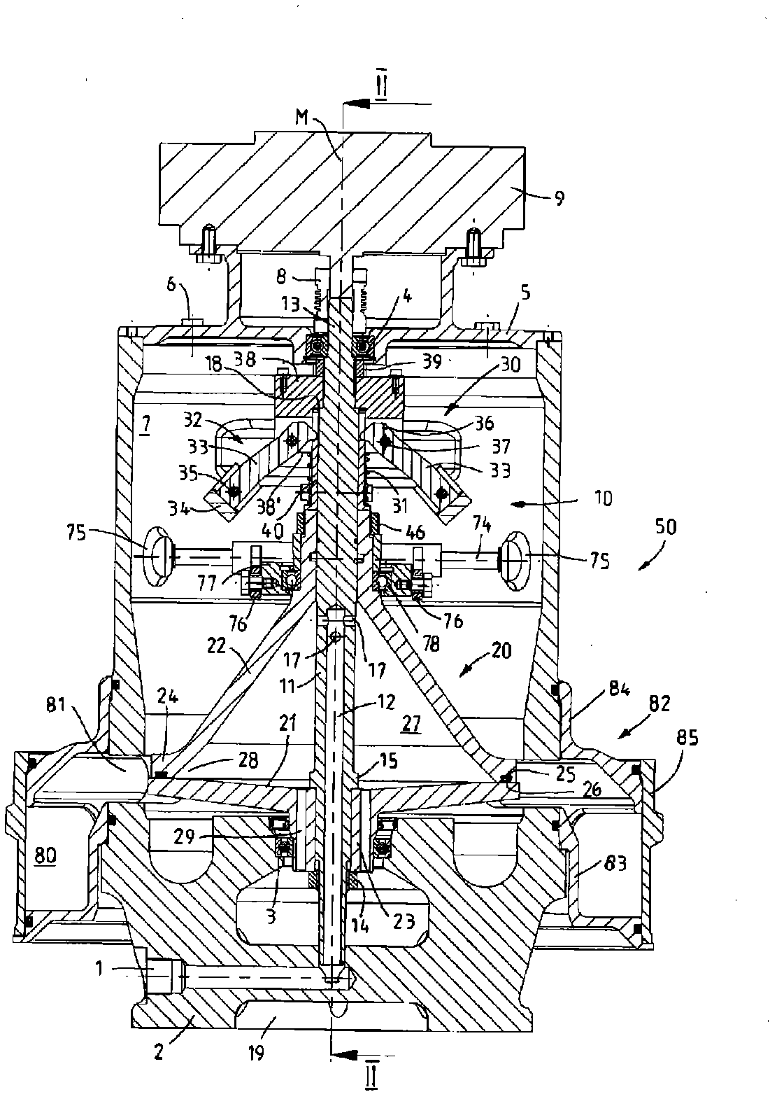
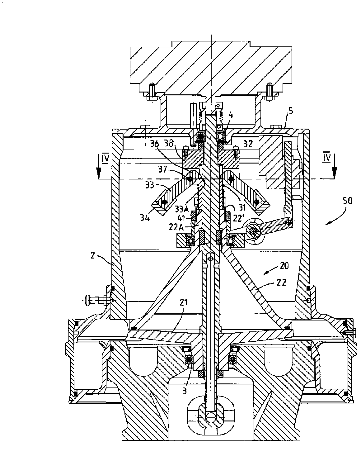
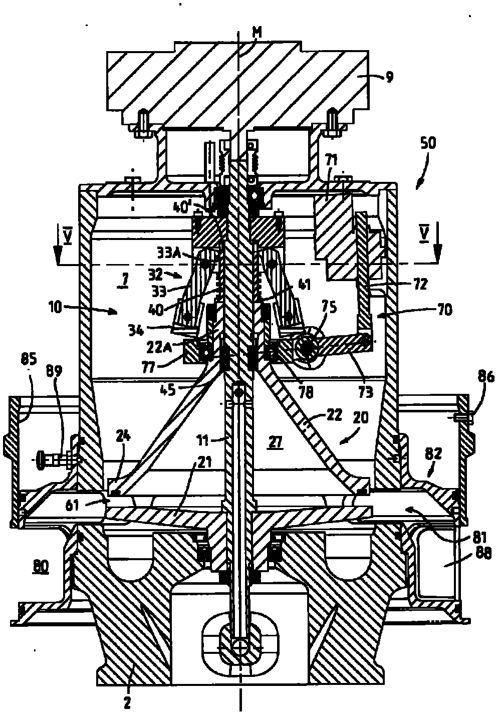
[0019] In these figures, reference numeral 50 generally designates a centrifuge according to the invention for separating solid matter or particles of solid matter from a liquid (for example, in particular a lubricating oil liquid) which can be passed through the centrifuge An inlet opening 1 in the seat part of the housing 2 is fed to the centrifuge 50 . From the inlet opening 1, the liquid to be separated flows into a duct 12, which is formed by the cavity of the rotor shaft 11, which is formed as a hollow shaft in the lower region of the centrifuge rotor, which is shown as a whole in the figure with Reference number 10 marks. The rotor shaft 11 extends approximately over the entire height of the centrifuge housing 2 and is arranged here substantially on the central axis M of the centrifuge housing 2 , which has an overall cylindrical design, the central axis M At the same time, the axis of rotation of the centrifuge rotor 10 is formed...


PUM


Abstract

The invention relates to a centrifuge for separating solids from a liquid, comprising a centrifuge rotor 10 with a rotor shaft 11, partially formed as a hollow shaft, and a centrifuging drum 20, being rotatable with the rotor shaft, wherein the liquid to be separated can be supplied via the cavity of the hollow shaft. To ease emptying of the drum, the centrifuging drum 20 comprises a drum lower part 21 and a drum upper part 22, which bears loosely against said drum lower part 21. The upper part 22 is guided in an axially movable manner on the shaft 11 and is movable by means of a disengagement mechanism 70 parallel to the rotor axis into an open position in which, for self-emptying of the interior space 27, the drum parts 21, 22 are spaced apart from one another while they still rotate with the rotor shaft 11.

Description

technical field [0001] The invention relates to a centrifuge for separating solid matter from a liquid, in particular from lubricating oil of an internal combustion engine, but also from other liquids containing solids to be separated by acceleration, the centrifuge having a centrifuge housing body, and has a centrifuge rotor, the centrifuge rotor includes a rotor shaft, the rotor shaft is rotatably mounted in the centrifuge housing and the rotor shaft can be driven by a separate drive and the rotor shaft is driven by Partly formed as a hollow shaft, and a centrifugal drum, which can rotate together with the rotor shaft, through which the hollow space of the hollow shaft can supply the inner space of the centrifugal drum with the liquid to be separated, and which is equipped with At least one outflow opening for liquid outflow from the interior space. The invention also relates to a centrifuge rotor for a centrifuge for separating solid matter from a liquid, in particular fro...

Claims


Application Information

Patent Timeline
Patent Type & Authority Applications(China)
IPC IPC(8): B04B5/00B04B13/00
CPCB04B5/005F01M2013/0422F01M2250/64F01M13/04B04B11/04B04B1/14
Inventor C·提策G·斯塔尔
Owner BOLL & KIRCH FILTERBAU GMBH
Learn More