Joint structure for toy

A technology of toys and joints, which is applied in the field of joint structures for toys, and can solve the problems of falling off of ball parts 101 and the inability to reduce the number of parts, so as to achieve the effect of reducing the number of parts and suppressing falling off

Inactive Publication Date: 2011-07-20
TOMY CO LTD
View PDF0 Cites 0 Cited by
  • Summary
  • Abstract
  • Description
  • Claims
  • Application Information

AI Technical Summary

Problems solved by technology

[0004] However, in such a ball joint structure, the ball member 101 and the swing members 100 and 102 as the sliding part must be provided separately, and the number of parts cannot be reduced.
In addition, when a force is applied to the ball member 101 in a direction in which the ball member 101 falls off from the other swing member 102, the ball member 101 may fall off relatively easily.

Method used


Image

  • Joint structure for toy
  • Joint structure for toy
  • Joint structure for toy

Examples


Embodiment Construction

[0037] Embodiments of the present invention will be described below with reference to the drawings.

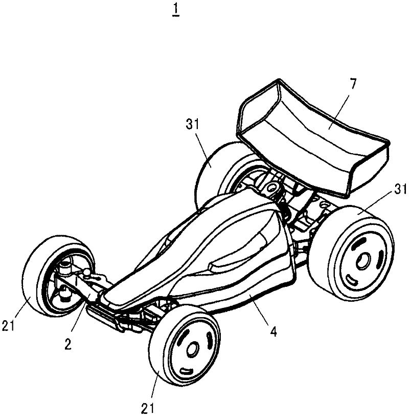
[0038] figure 1 It is an external view of a car toy 1 having a joint structure for a toy according to the present invention.

[0039] As shown in this figure, the car toy 1 is a traveling toy that simulates an off-road vehicle, and has a front wheel axle 2 supporting the front wheels 21, 21 so as to be able to swing left and right, and a rear wheel axle 3 supporting the rear wheels 31, 31 (refer to Figure 5 ), body 4, and wing member 7.

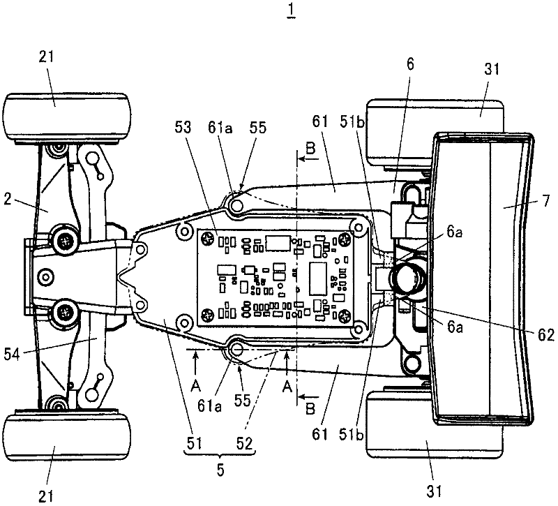
[0040] figure 2 It is a top view of the car toy 1 with the vehicle body 4 removed.

[0041] As shown in the figure, the front wheel axle 2 is supported on the front wheel chassis 5 , and the rear wheel axle 3 is supported on the rear wheel chassis 6 .

[0042] Among them, the chassis 5 for the front wheels is a substantially flat bottom chassis 51 for the front wheels and a chassis 52 for the upper front wheels ( figure 2 The lower f...


PUM


Abstract

A joint structure for toy can reduce the number of components and prevents dropping-off of a sliding part. In the joint structure for toy, which connects an arm part (61) and a chassis (5) for a front wheel asway with each other, a top end (61a) of the arm part (61) is provided with a first dent part (61b) and a second projection (61c) which are provided with central axes in a vertical direction and are formed to semi-spheres that are concentric with each other. The chassis (5) for the front wheel is provided with a chassis (52) for an upper front wheel, which is provided with a semi-spheric first projection (52a) that corresponds to the first dent part (61); and the chassis is also provided with a chassis (51) for a lower front wheel, which is provided with a semi-spheric second dent part (51a) which corresponds with the second projection (61c). Furthermore the top end (61a) of the arm part (61) is clamped through the chassis (52) for the upper front wheel and the chassis (51) for the lower front wheel. Therefore the first projection (52a), the first dent part (61n), the second projection (61c) and the second dent part (51a) can slide respectively.

Description

technical field [0001] The invention relates to a joint structure for toys. Background technique [0002] Conventionally, a so-called ball joint structure has been known as a toy joint structure in which two members are relatively swingably connected, such as Figure 9 As shown, a spherical ball member 101 attached to one swing member 100 is fitted into an arcuate sliding surface 102a formed on the other swing member 102 (for example, refer to Patent Document 1). [0003] [Patent Document 1] Patent No. 3798350 [0004] However, in such a ball joint structure, the ball member 101 as a sliding part and the swing members 100 and 102 must be provided separately, and the number of parts cannot be reduced. In addition, when a force is applied to the ball member 101 in a direction in which the ball member 101 falls off from the other swing member 102, the ball member 101 may fall off relatively easily. Contents of the invention [0005] The present invention has been made in vi...

Claims


Application Information

Patent Timeline
IPC IPC(8): A63H31/00
CPCA63H30/04A63H13/18A63H17/262Y10T403/32631
Inventor 中山贤二永井智人
Owner TOMY CO LTD
Why Eureka
Try Eureka