Filter cleaning device and drier

A cleaning device and filter technology, which is applied in the direction of dryer, drying, dispersed particle filtration, etc., to achieve the effect of reducing the number of parts

Inactive Publication Date: 2018-04-27
KOWA CO LTD
View PDF1 Cites 0 Cited by
  • Summary
  • Abstract
  • Description
  • Claims
  • Application Information

AI Technical Summary

Problems solved by technology

[0005] However, according to the filter cleaning device described in the above patent document 1, since the connection mechanism of the cover and the first pre-filter linked with the action of the cover is located inside the front box of the main body, dust adheres to the connection mechanism and causes possibility of failure

Method used


Image

  • Filter cleaning device and drier
  • Filter cleaning device and drier
  • Filter cleaning device and drier

Examples


Embodiment Construction

[0061] Hereinafter, embodiments of the present invention will be described with reference to the drawings. In addition, this invention is not limited to the said embodiment.

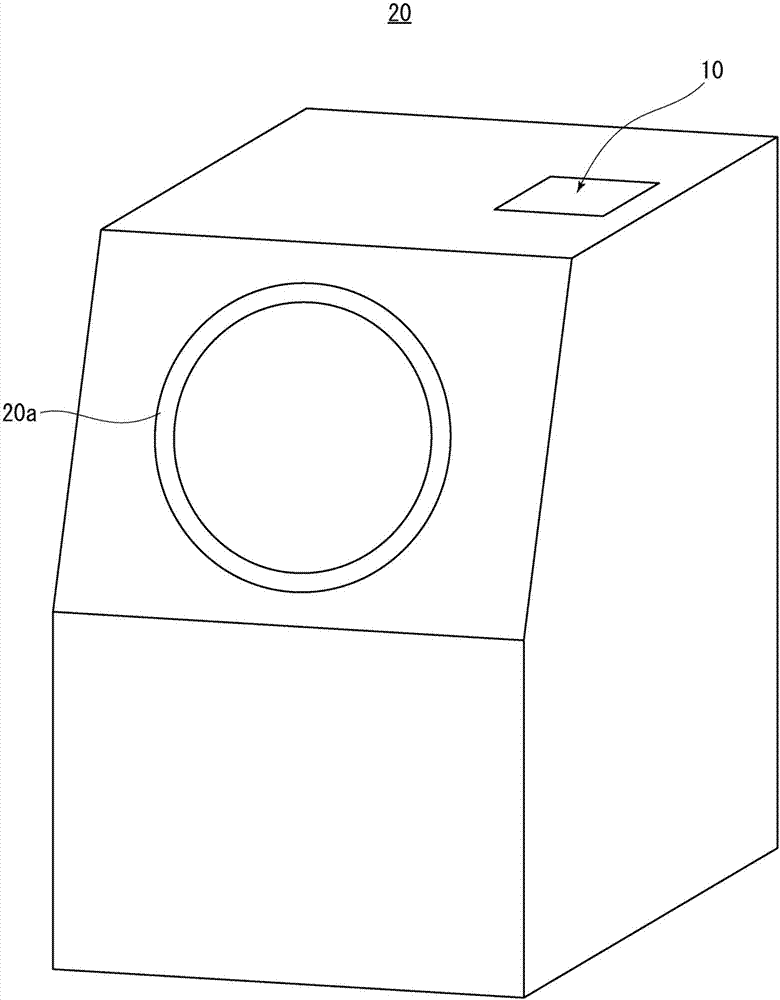
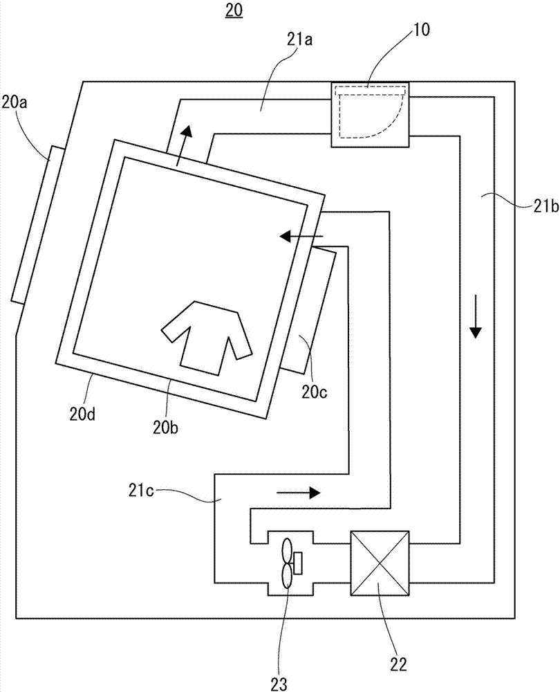
[0062] figure 1 is a perspective view showing the dryer of the present invention, figure 2 It is a sectional view showing the internal structure of the dryer. The dryer of the present invention will be described using the above-mentioned figures. The dryer 20 of the present invention is equipped with a door 20a on the front surface, and a rotary drum 20b is rotatably arranged in a tank body 20d to accommodate clothes and other to-be-dried items. The wind is circulated and supplied into the rotary drum 20b through the circulation pipes 21a, 21b, 21c so as to dry the to-be-dried objects, and the filter cleaning device 10 is arranged at the outlet of the circulation pipes 21a, 21b, 21c exhausted from the tank body 20d. side.


PUM


Abstract

The invention provides a filter cleaning device and a drier. The filter cleaning device comprises a compact movable mechanism with small size and can prevent dust to be attached to the movable mechanism. The movable mechanism (7) of the filter cleaning device (10) comprises an operation rod (7a), a motion transfer member (7b) for transferring the motion transferred from the operation rod (7a) to acleaning member, and a pressing portion (6c) formed on a dust discharge suppression member (6) and used for pressing the operation rod (7a). The movable mechanism is set to enable the direction of along edge of the operation rod (7a) and the direction vertical to the thickness direction of the motion transfer member (7b) to be parallel to an outer side surface (2a) of a cleaning device main body(2).

Description

technical field [0001] The present invention relates to a filter cleaning device for removing dust adhering to a filter, and a dryer provided with the filter cleaning device. Background technique [0002] Conventionally, there is known a filter cleaning device which is provided with a filter for collecting dust and removes the dust adhering to the filter (Patent Document 1). [0003] The filter cleaning device of Patent Document 1 is installed in an electric vacuum cleaner, and a detachable plastic bag is arranged at a predetermined position on the front body of the main body. In order to store dust in the plastic bag, the first pre-filter is rotatable. It is integrally provided with the cover covering the plastic bag from the rear, and when the cover is opened, the dust of the first pre-filter is accommodated in the plastic bag, and the second pre-filter is arranged in the front box of the main body On the wall, the first pre-filter is in sliding contact with the second pr...

Claims


Application Information

Patent Timeline
IPC IPC(8): B01D46/10F26B11/02F26B21/00F26B25/08
CPCB01D46/10F26B11/02F26B21/001F26B21/003F26B25/08B01D46/681
Inventor 横山広
Owner KOWA CO LTD
Why Eureka
Try Eureka