Pipe connector

A connector and force technology, applied in the direction of sleeve/socket connection, pipe/pipe joint/pipe fitting, coupling, etc., to achieve the effect of fewer parts and simple parts

Active Publication Date: 2013-03-06
NIFCO INC
View PDF5 Cites 0 Cited by
  • Summary
  • Abstract
  • Description
  • Claims
  • Application Information

AI Technical Summary

Problems solved by technology

[0002] Conventionally, as such a connector for connecting tubes, there is known a device including a connector body into which the tube is inserted and removed, and a lock member slidably held on the connector body to fix the inserted tube, A retaining arm having a hook held in a hole opened on the peripheral surface of the connector main body and displaceable in the radial direction of the connector is formed on the locking member, and the hook has a The inclined surface, when the locking member moves in the direction of fixing the pipe, engages with the protrusion of the pipe to fix the pipe, and the inclined surface is pressed by the periphery of the hole of the connector body, thereby restricting its radial movement ( Refer to Patent Document 1)

Method used


Image

  • Pipe connector
  • Pipe connector
  • Pipe connector

Examples


no. 1 approach >

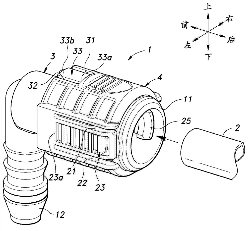
[0039] Below, refer to Figure 1 to Figure 8 , the pipe coupling connector according to the first embodiment of the present invention will be described. In the following, unless otherwise specified, the direction of the connector for pipe connection and the pipe is based on figure 1 It is determined by the direction indicated by the arrow in .

[0040] Such as figure 1 As shown, a tube connecting connector (hereinafter referred to simply as a connector) 1 is used to connect a tube 2 for fluid transport to a connection object (here, a hose for fluid transport not shown in the figure), and is mainly composed of The connector body 3 into which the tube 2 is inserted and removed is composed of a lock member 4 which is held movably in the front-rear direction by the connector body 3 and which fixes and releases the tube 2 in accordance with its forward-backward movement.

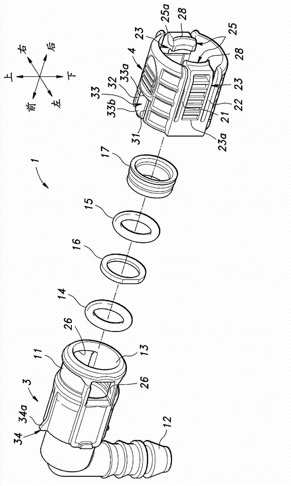
[0041] The connector main body 3 is made of synthetic resin material, and as figure 2 As shown, it includ...

no. 2 approach >

[0054] Next, refer to Figure 9 ~ Figure 13 , the pipe coupling connector of the second embodiment will be described. exist Figure 9 ~ Figure 13 In , the same symbols are assigned to the same components as those in the first embodiment. In addition, in the second embodiment, regarding the same matters as those in the first embodiment, a detailed description thereof will be omitted below except for matters mentioned in particular.

[0055] Such as Figure 9 As shown, the locking member 4 has a pair of curved arm-shaped elastic urging pieces 33 extending from the upper center to the left and right downwards, and a pair of elastic urging pieces 33 arranged between these elastic urging pieces 33 and extending downward from the upper center. Pin-shaped locking piece 23. Engagement claws 51 are respectively formed at free ends of the elastic biasing pieces 33 . In the second embodiment, the locking piece 23 has a structure that is hardly elastically deformable. In addition, t...

no. 3 approach >

[0063] Next, refer to Figure 14 ~ Figure 17 , the pipe connection connector of the third embodiment will be described. exist Figure 14 ~ Figure 17 In , the same symbols are assigned to the same components as those in the first embodiment. In addition, in the third embodiment, the same items as those in the first embodiment will not be described in detail below except for the items mentioned in particular.

[0064] Such as Figure 14 as well as Figure 15 As shown, the locking member 4 has a symmetrical shape up and down and left and right, and a pair of left and right elastic locking pieces 23 protrude from the annular portion 4b on the front end side toward the rear. As in the case of the first embodiment, the elastic locking piece 23 can be elastically deformed with the front base end portion 23a connected to the annular portion 4b as a fulcrum, so that the locking claw 25 can move in the radial direction (left-right direction) of the locking member 4. ) shift up. In...


PUM


Abstract

A pipe connector which can securely maintain the connection of a pipe to the pipe connector. A pipe connector (1) comprises: a connector body (3) into and from which a pipe (2) is inserted and removed; a lock member (4) which has a pipe engagement section (23) for engaging with the pipe and which is held by the connector body in such a manner that the lock member (4) can move between a lock position at which the pipe engagement section engages with the pipe and a disengagement position at which the engagement is disengaged; and pressing means (33, 41) for pressing the lock member toward the lock position. The pipe engagement section is configured so that, when the lock member is located at the lock position, the pipe engagement section is pressed by the pressing force of the pressing means in the direction in which the pipe engagement section engages with the pipe.

Description

technical field [0001] The present invention relates to a pipe connecting connector for connecting a pipe to a connection object. Background technique [0002] Conventionally, as such a connector for connecting tubes, there is known a device including a connector body into which the tube is inserted and removed, and a lock member slidably held on the connector body to fix the inserted tube, A retaining arm having a hook held in a hole opened on the peripheral surface of the connector main body and displaceable in the radial direction of the connector is formed on the locking member, and the hook has a The inclined surface, when the locking member moves in the direction of fixing the pipe, engages with the protrusion of the pipe to fix the pipe, and the inclined surface is pressed by the periphery of the hole of the connector body, thereby restricting its radial movement ( Refer to Patent Document 1). [0003] In addition, in this conventional connector, when the release ar...

Claims


Application Information

Patent Timeline
IPC IPC(8): F16L37/12
CPCF16L37/0985F16L37/12F16L37/144F16L21/06F16L21/08F16L37/084
Inventor 冈崎刚
Owner NIFCO INC
Why Eureka
Try Eureka