Electronic device

A technology for electronic equipment and resistance elements, applied in the field of electronic equipment operated in multiple directions, can solve the problem of difficulty in reducing the number of parts, and achieve the effect of reducing the number of parts and good operability

Inactive Publication Date: 2006-12-20
PANASONIC CORP
View PDF0 Cites 0 Cited by
  • Summary
  • Abstract
  • Description
  • Claims
  • Application Information

AI Technical Summary

Problems solved by technology

Although the switch with the above-mentioned structure has a thin shape, four separate switches are used, and there is a problem that all the structural parts of the four switches are necessary, and it is difficult to reduce the number of parts.

Method used


Image

  • Electronic device
  • Electronic device
  • Electronic device

Examples


Embodiment approach

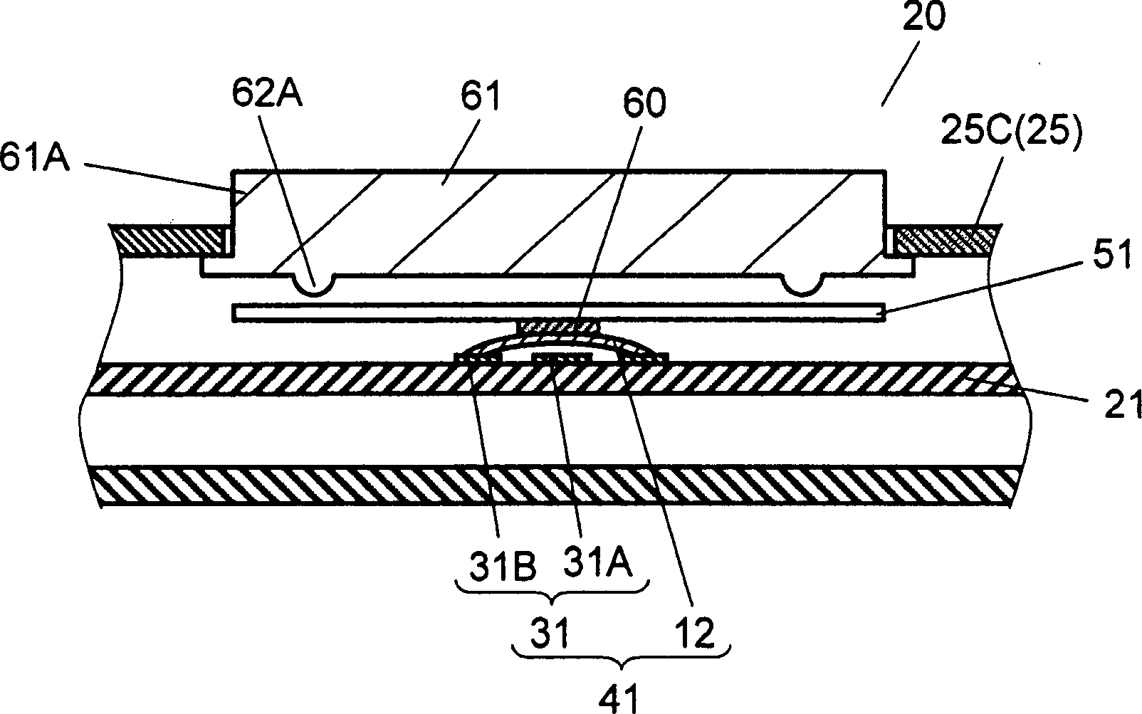
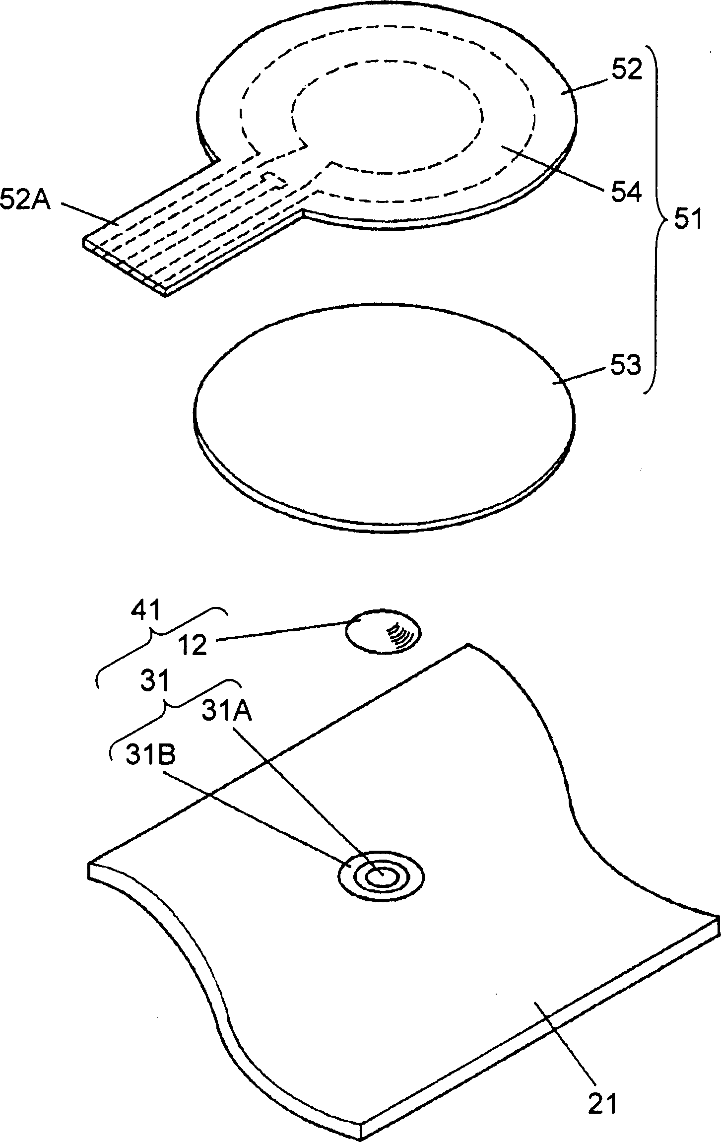
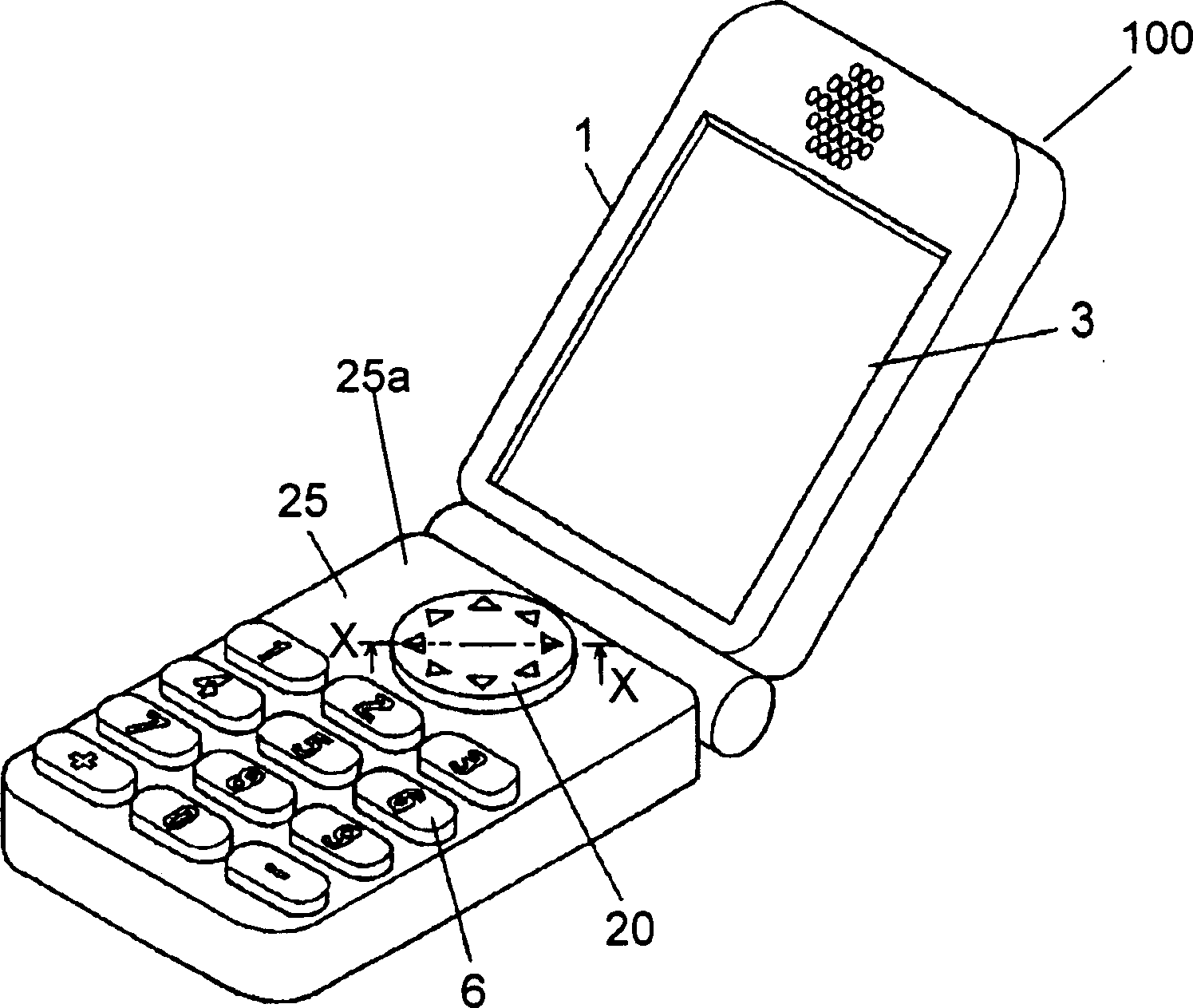
[0041] figure 1 It is a sectional view of the multi-directional operation part of the mobile phone 100 according to the embodiment of the present invention, figure 2 is an exploded perspective view of the same multi-directional operation part, and image 3 It is a perspective view of the appearance of the same device. also, figure 1 right image 3 The cross-section of the X-X line is illustrated.

[0042] Such as figure 1As shown, the multi-directional operation unit 20 of the mobile phone 100 has: a pad 51 capable of detecting the operation coordinate position by touch operation and only one push switch 41 disposed at the center below it.

[0043] In addition, the multi-directional operation unit 20, such as image 3 As shown, in the mobile phone 100 , the second housing 25 foldably connected to the first housing 1 having the display unit 3 via a hinge mechanism is disposed at a front position on the upper surface of the second housing 25 . In addition, the point t...


PUM


Abstract

An electronic device includes a pad which can detect an operating coordinate position by a touch operation, and a single push-switch provided under the pad. A touch operation to the pad at a given place allows a preliminary announcement of a function, and a further press-down of the pad being kept at the same position prompts the push-switch to work and determine the function preliminary announced. This structure allows excellent operability, and a single push-switch allows reducing the number of components of the operating section, so that the electronic device having these advantages is obtainable.

Description

technical field [0001] The present invention mainly relates to electronic equipment such as AV equipment and OA equipment, and particularly relates to electronic equipment that can be operated in multiple directions. Background technique [0002] In recent years, with the development of various electronic devices, excellent operability is required. In addition, portable electronic devices such as mobile phones and digital cameras are required to be smaller, lighter and more functional, and at the same time, emphasis is placed on improving usability. [0003] Hereinafter, a mobile phone will be described as an example among conventional electronic devices. [0004] Figure 11 It is a perspective view of the appearance of a general mobile phone. [0005] Such as Figure 11 As shown, the portable phone is composed of a first frame body 1 and a second frame body 2 in a foldable manner via a hinge mechanism. The display unit 3 is arranged on the inner surface side of the first...

Claims


Application Information

Patent Timeline
IPC IPC(8): H01H13/00H01C10/00G06F3/01
CPCG06F3/0338H04M2250/22H01H25/041G06F3/03547
Inventor 泽田昌树井上浩人山本保
Owner PANASONIC CORP
Why Eureka
Try Eureka