Supercharge Your Innovation With Domain-Expert AI Agents!

Uplink power compression method and user equipment

A user equipment, power technology, applied in power management, location diversity, electrical components and other directions, can solve problems such as power limitation

Inactive Publication Date: 2011-07-20
POTEVIO INFORMATION TECH
View PDF0 Cites 6 Cited by
  • Summary
  • Abstract
  • Description
  • Claims
  • Application Information

AI Technical Summary

Problems solved by technology

[0010] In view of this, the purpose of the embodiments of the present invention is to provide an uplink power compression method and user equipment, so as to solve the problem of power limitation when two or more uplink channels are used for uplink transmission

Method used


Image

  • Uplink power compression method and user equipment
  • Uplink power compression method and user equipment
  • Uplink power compression method and user equipment

Examples


no. 1 example

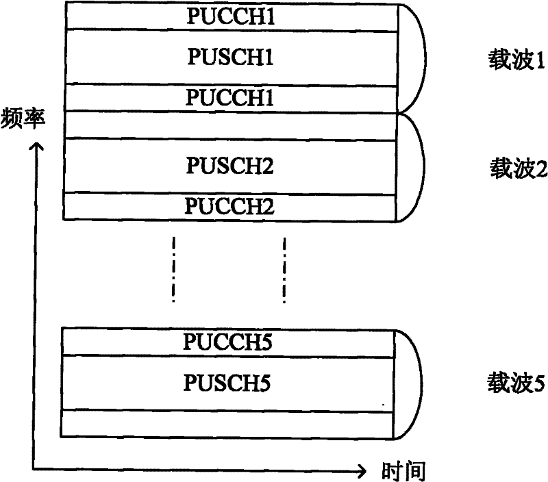
[0037] In the first embodiment, the user equipment uses a total of 5 uplink carriers, and each uplink carrier carries both PUCCH and PUSCH. For details, please refer to figure 1 , 2 and 3.

[0038] figure 1 It is a time slot distribution diagram of using multiple PUSCHs and PUCCHs for uplink information transmission at the same time, which only gives an example of the time slot distribution for using multiple PUSCHs and PUCCHs for uplink information transmission at the same time. For PUSCHs and PUCCHs that exist simultaneously All situations are applicable, and are not used to limit the specific slot distribution of PUSCH and PUCCH.

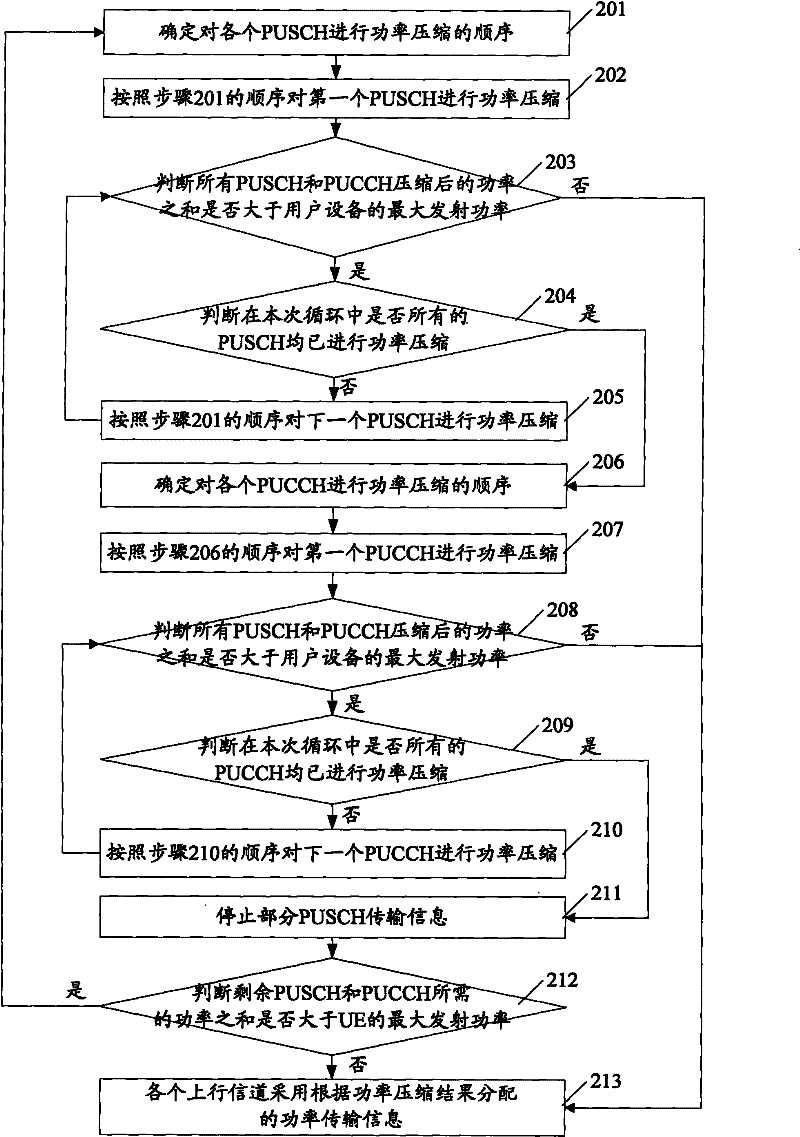
[0039] figure 2 It is a flow chart of the first method of uplink power compression provided by the present invention.

[0040] see figure 2 , the first method specifically includes:

[0041] Step 201, determine the order of performing power compression on each PUSCH.

[0042] In this step, the order of sounding reference signals (Sounding ...


PUM


Abstract

The embodiment of the invention discloses a power compression method and user equipment. The method comprises the following steps of: transmitting information by employing more than two uplink channels, and performing power compression on partial or all uplink channels when the sum of the needed power of various uplink channels is greater than the maximum transmitting power of the user equipment, until the sum of the compressed power of the various uplink channels is not greater than the maximum transmitting power of the user equipment, wherein the partial or all uplink channels transmit information by using the compressed power respectively. The invention can solve the problem of power limitation when the user equipment transmits the information through more than two uplink channels.

Description

technical field [0001] The present invention relates to the technical field of mobile communication, in particular to an uplink power compression method and user equipment. Background technique [0002] In a mobile communication system, when a user equipment (UE) performs uplink transmission, it calculates the power required for uplink transmission according to a predetermined method. If the calculated power is greater than the maximum transmit power of the UE, the UE cannot transmit according to the required power. For uplink transmission, this situation is called UE power limitation, wherein the maximum transmission power refers to the maximum transmission power determined according to the UE type or the power owned by the UE. [0003] There is a big difference between uplink transmission and downlink transmission, one of which is very important: during uplink transmission, due to the continuous consumption of UE power and the inability to replenish energy in time, UE is p...

Claims


Application Information

Patent Timeline
IPC IPC(8): H04W52/14H04W52/36
CPCH04W52/367H04B7/022H04W52/146Y02B60/50H04W52/346
Inventor 张元雨郑辰
Owner POTEVIO INFORMATION TECH
Features
  • R&D
  • Intellectual Property
  • Life Sciences
  • Materials
  • Tech Scout
  • Unparalleled Data Quality
  • Higher Quality Content
  • 60% Fewer Hallucinations
Learn More